. 2023 Feb 4;13(1):2065.
doi: 10.1038/s41598-023-29092-z.

The restoration and erection of the world's first elevated obelisk

Affiliations

The restoration and erection of the world's first elevated obelisk

Atef M Saleh et al. Sci Rep. .

Abstract

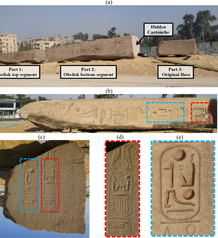
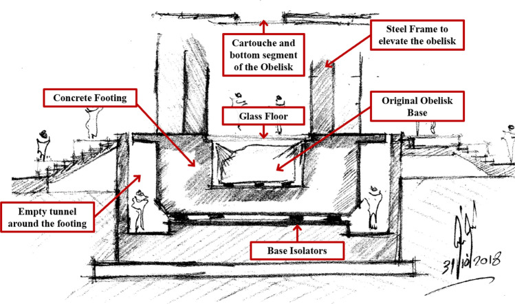
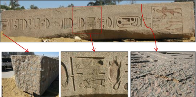
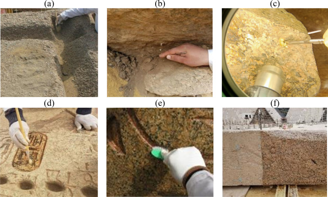
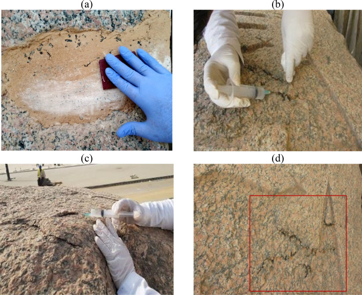
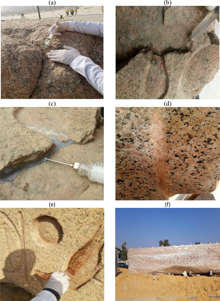
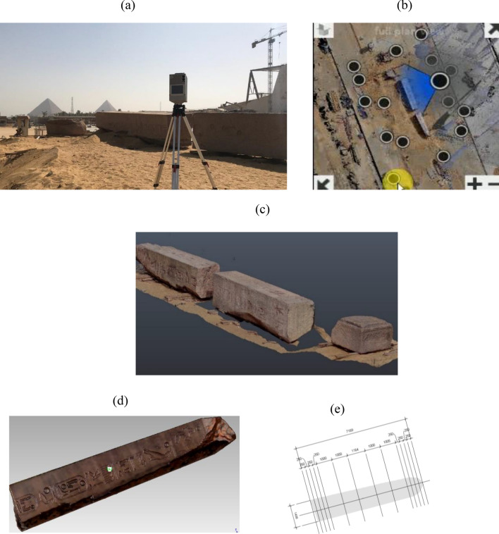
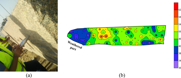
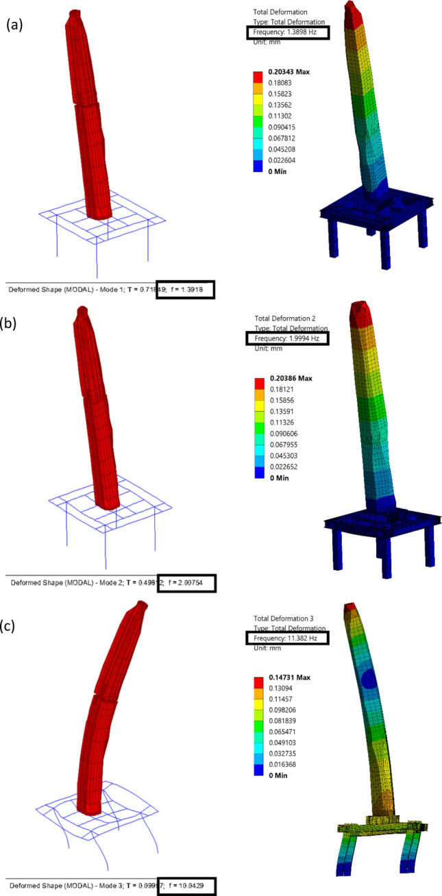
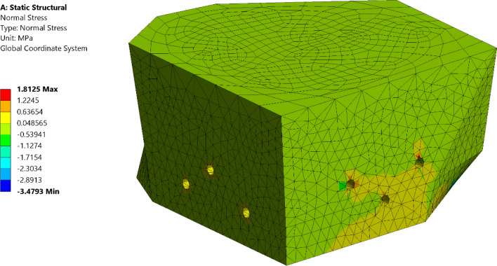
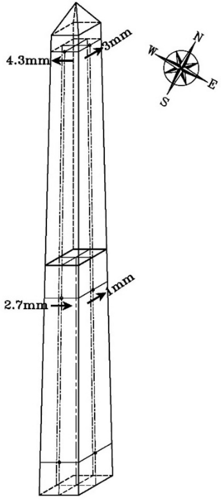
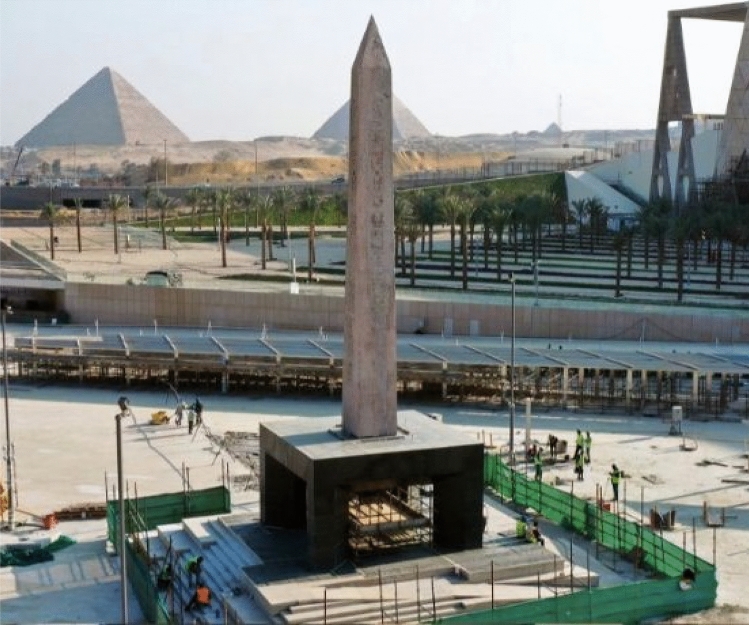
Obelisks presented an important element in the architecture of ancient Egypt. This research is concerned with the re-erection of an obelisk that belongs to the famous Pharoah Ramses II. It was found broken and was transported to the Grand Egyptian Museum for restoration and display. An observation of Ramses II Cartouche at the bottom side of the obelisk base inspired the authorities to provide an innovative architectural design to display the obelisk elevated. The supporting structure was designed to allow the visitors to walk underneath the obelisk and observe Ramses II's signature. The idea of elevating the obelisk presented several challenges including evaluating the obelisk's current condition, restoration and fixation methodology, structural stability, and uncertainties of material characteristics, amongst others. To control the obelisk deformations under lateral loading, state-of-the-art base isolators were introduced. For the task to be achieved, a multidisciplinary team including historians, conservators, archaeologists, architects, and engineers with different specialties was appointed. The team performed the task successfully and currently, the obelisk stands at the entrance piazza of the Grand Egyptian Museum representing the world's first elevated obelisk.


Conflict of interest statement

The authors declare no competing interests.

Figures

Figure 1
Figure 1
The Obelisk of Ramses II found at San Elhagar. (a) The obelisk was found broken into two pieces and separated from the base. (b) The top piece of the obelisk with hieroglyphic carvings. (c) The cartouche at the bottom face of the obelisk has the names of King Ramses II, which are the same carvings shown on the obelisk side. (d) carvings Birth name: Ra-ms-sw mry-Imn “Born is the God Ra, beloved of Amun”. (e) Name of the throne (patron surname): Wsr-mAat-Ra stp-n-Ra "Strong is the justice of Ra, the chosen one of Ra".
Figure 2
Figure 2
Schematic concept of the elevated obelisk by Atef M. Saleh.
Figure 3
Figure 3
Areas of the obelisk that suffer from flaking, spotting, laminating, and transformation of feldspar minerals into clay minerals, as well as clay deposits that distort the appearance of the obelisk and their inscriptions.
Figure 4
Figure 4
Procedures of mechanical and chemical cleaning (a) Removal of sand and mud deposits by brush, (b) Removal of sticky mud deposits by scalpel, (c) Removal of salt deposits by scalpel under eyepiece, (d) Chemical cleaning by a mixture consisting of distilled water and ethyl alcohol, (e) Washing the stone by distilled water, The brush indicates the red color of the royal cartouche of King Ramesses II (f) Showing a part of the obelisk before chemical cleaning, in the left, and a part of the obelisk after chemical cleaning, in the right.
Figure 5
Figure 5
Treatment of granular disintegration and cementation process of separated crusts (a) Treatment of granular disintegration, (b) Cementing the crusts of small size, (c) Cementing the crusts of medium size, (d) Completion of the injection process using Paraloid B72 before total drying of the partially detached crusts.
Figure 6
Figure 6
Steps of injection and filling of cracks and gaps, as well as consolidation of colored parts (a) Injection of cracks by Paraloid B 72, (b) Injection of wide fractures by Paraloid B 72 in high concentration, (c) During the application of Micro balloons, (d) Using a mortar consisting of granite powder, Micro balloons, Paraloid B72 and small percentage of natural inorganic oxide in order to filling the gabs, (e) Consolidation of the red colored parts, (f) Covering the obelisk with polyethylene after initial fine restoration, preparing for the assembly and erection processes.
Figure 7
Figure 7
3D laser scanning and modeling of the obelisk. (a) Measurements using a Terrestrial Laser Scanner. (b) Processing scanned data. (c) Registering a point cloud of the obelisk. (d) Textured 3D models of the obelisk. (e) Extracting obelisk properties.
Figure 8
Figure 8
The rebound hammer testing. (a) Field work of rebound hammer testing. (b) the result represented as a contour map.
Figure 9
Figure 9
The Thermal imaging investigation. (a) the field work of thermal imaging. (b) an example of the produced thermal images.
Figure 10
Figure 10
GPR measurements on the obelisk. (a) Field work of GPR. (b) an example of the GPR results.
Figure 11
Figure 11
Results of XRD and XRF tests on a fallen sample from the obelisk. (a) the mineral composition represented in 3D pie chart. (b) the chemical composition represented in a pie chart.
Figure 12
Figure 12
SEM and petrography of a fallen sample from the obelisk. (a) interpretation on SEM photo. (b) interpretation on petrography photo.
Figure 13
Figure 13
Pull out laboratory testing. (a) pull-out testing of an anchor. (b) displacement load representation of the anchors.
Figure 14
Figure 14
Granite laboratory testing. (a) granite sample under compression machine. (b) stress–strain curve of uniaxial and triaxial testing with average modulus of elasticity.
Figure 15
Figure 15
Geometric description of the different elements of the obelisk, and a comparison of the seismic response for three different base design cases, which are (a) Obelisk fixed on concrete base. (b) Obelisk fixed on steel frame supported on concrete base. (c) Obelisk fixed on steel frame supported on concrete base with base isolation.
Figure 16
Figure 16
(a) The anchor connection of the two parts of the obelisk, (b) The anchor connection between the obelisk and the bottom steel frame, (c) the steel cage from the ANSYS model.
Figure 17
Figure 17
Comparison of natural frequencies between SAP2000 model on the left and ANSYS model on the right for, (a) Mode, (b) Mode 2, (c) Mode 3.
Figure 18
Figure 18
Tensile stresses in the obelisk due to thermal loads.
Figure 19
Figure 19
Actual inclination after erection.
Figure 20
Figure 20
Obelisk after erection on its elevated platform.

References

    1. Habachi L. The Obelisks of Egypt—Skyscrapers of the Past. Cairo Press: The American University; 1984.
    1. Curran, B. A. Obelisks in ancient egypt. In Encyclopaedia of the History of Science, Technology, and Medicine in Non-Western Cultures. Springer, 1773–1785 (2008). 10.1007/978-1-4020-4425-0_8815
    1. Parker J.H. The Archaeology of Rome, Vol. 4: The Egyptian Obelisks. James Parker and Co., Oxford (1876).
    1. Corringe HH. Egyptian Obelisks. G.P. Putnam’s Sons; 1882.
    1. Brier B. The secret life of the Paris obelisk. Aegyptiaca. J. Hist. Recept. Ancient Egypt. 2018;2:75–91. doi: 10.1188/aegyp.2018.2. - DOI