. 2023 Feb 6;14(1):633.
doi: 10.1038/s41467-023-36342-1.

Pulse-driven self-reconfigurable meta-antennas

Affiliations

Pulse-driven self-reconfigurable meta-antennas

Daiju Ushikoshi et al. Nat Commun. .

Abstract

Wireless communications and sensing have notably advanced thanks to the recent developments in both software and hardware. Although various modulation schemes have been proposed to efficiently use the limited frequency resources by exploiting several degrees of freedom, antenna performance is essentially governed by frequency only. Here, we present an antenna design concept based on metasurfaces to manipulate antenna performances in response to the time width of electromagnetic pulses. We numerically and experimentally show that by using a proper set of spatially arranged metasurfaces loaded with lumped circuits, ordinary omnidirectional antennas can be reconfigured by the incident pulse width to exhibit directional characteristics varying over hundreds of milliseconds or billions of cycles, far beyond conventional performance. We demonstrate that the proposed concept can be applied for sensing, selective reception under simultaneous incidence and mutual communications as the first step to expand existing frequency resources based on pulse width.


Conflict of interest statement

The authors declare no competing interests.

Figures
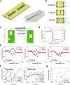
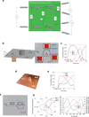
Fig. 1
Fig. 1. Fundamental Single-Line System.
a Simulation model and measurement sample. Ordinary grounded monopole transmitters (Tx) and receivers (Rx) were connected by waveform-selective metasurface lines to vary surface wave propagation and exhibit ultratransient responses at the same frequency. b Circuit configurations for C-based, L-based and parallel waveform-selective metasurfaces. Design parameters are seen in Supplementary Fig. S1, Supplementary Tables S1 and  S2. c Simplified equivalent circuit concept representing the two monopole antennas (Tx and Rx) connected by the waveform-selective metasurface line. d Simulated reflectance of the monopoles and normalized spectrum of a 50-ns sine wave pulse of 2.42 GHz. e Simulated transmittances between the antennas connected by (left) C-based, (center) L-based, and (right) parallel-type waveform-selective metasurface lines as a function of frequency with a 10 dBm input power. In the legend, CW represents a continuous wave as a sufficiently long pulse, while Pulse indicates a 50-ns-long short pulse (see Supplementary Fig. S6 for a comparison to an intermediate pulse of 300 ns). f The corresponding transient transmittances at 2.4 GHz in the (left) simulation and (right) measurement (also see Supplementary Fig. S6 for simulated transmittances with variation of pulse width). g Measured results using larger capacitances for the C-based waveform-selective metasurface line. C was increased from 1 to 1 μF and 100 μF.
Fig. 2
Fig. 2. Combined selective multiline systems and associated performance.
a Extended equivalent circuit concept using additional waveform-selective metasurface lines to selectively transmit signals. Three variable transmission lines ZC, ZL, and ZP represented C-based, L-based and parallel waveform-selective metasurface lines, while Z1, Z2, and Z3 were impedances of three receivers Rx1, Rx2, and Rx3. b Monopole transmitter connected by all three types of waveform-selective metasurface lines. c (left) Simulated and (right) measured transmittances to Rx1, Rx2, and Rx3. The frequency was set to 2.36 GHz and 2.45 GHz in the simulation and measurement, respectively, while the input power was fixed at 15 dBm in both cases. d Image of a prototype with three waveform-selective metasurfaces fully extended on a 2D surface to vary radiation characteristics over the entire surface. e Corresponding measured transmittances at 2.24 GHz with 23 dBm. Note that the 2D metasurface case had a lower operating frequency due to a higher number of electronic circuits soldered to hexagonal patch sides, which introduced more parasitic elements.
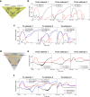
Fig. 3
Fig. 3. System for free-space wave control.
a Simplified equivalent circuit concept. A transmitter was expressed by an AC source, a switch, and input impedance Z0. C-based, L-based, and parallel waveform-selective metasurfaces were respectively represented by variable shunt impedances ZC, ZL, and ZP between transmission lines that correspond to free space or vacuum. Z1, Z2, and Z3 were impedances of three receivers. b Simulation model. A grounded monopole transmitter (effectively working as a dipole suspended in free space) was surrounded by six panels, comprising two C-based, two L-based and two parallel-type waveform-selective transmitting metasurfaces (or slit structures introduced in Supplementary Figs. S13 and  S14). The distance between the transmitter (Tx) and the receivers (Rx1-Rx3) was 200 mm. c Simulated transmittance at 3.85 GHz with 30 dBm (see Supplementary Fig. S16 for frequency-domain profiles). d Experimental sample designed based on the simulation model above. e Experimental measurement results at 3.85 GHz with 30 dBm. f Schematic for measurement of the antenna radiation pattern where the metasurface hexagonal prism was rotated counter clock-wise forming an angle ϕ to the Tx-Rx line. In the current schematic ϕ = 60°. Also, in this schematic, the C-based, L-based and parallel waveform-selective metasurface panels were represented by the same colors as the ones used in (b). g Time-varying radiation patterns of the metasurface antenna in (left) polar coordinate system and (right) Cartesian coordinate system, where the right axis represents a comparison to ideal directive condition. Detailed information on the ideal directive condition is presented in Supplementary Fig. S17.
Fig. 4
Fig. 4. Passive variable sensor to detect the location of scattering objects.
a Antenna system used in Fig. 3 in close proximity to a copper plate (70 mm wide and 51 mm tall). The distance between the copper plate and the closest waveform-selective metasurface panels was set to 1.0 cm as a default value. The frequency and power were 3.85 GHz and 30 dBm, respectively. b Measurement results when the copper plate was deployed in front of either the C-based, L-based, or parallel waveform-selective metasurface panels. Additional measurement results using two copper plates with (c) the same distances and (d) different distances. d The distance between one of the copper plates and the L-based waveform-selective metasurface was set to either 1.0 cm or 9.4 cm, while the distance between another plate and the parallel waveform-selective metasurface was fixed at 1.0 cm.
Fig. 5
Fig. 5. Selective reception under simultaneous incidences.
a Simulation model using three external monopoles as transmitters. The center monopole selectively received different signals due to the presence of different waveform-selective transmitting metasurfaces. Frequency and input power were 3.85 GHz and 30 dBm, respectively. b Transmittances using (left) only one external transmitter and (right) more than one external transmitter. c Received voltages in different time slots. d Experimental sample and corresponding (e) transmittances and (f) received voltages with input power adjusted to 36 dBm. The distance between the transmitters (Tx1–Tx3) and the receiver (Rx) was 70 mm. Additional simulation results are shown in Supplementary Fig. S23, where the distance between the transmitters and the receiver was increased to 200 mm to represent a more realistic far-field distance.
Fig. 6
Fig. 6. Mutually pulse-width-selective communication system.
a Simulation model using three antennas connected by either C-based, L-based or parallel waveform-selective metasurface line. The frequency and input power were set to 2.36 GHz and 10 dBm, respectively. b Simulation results of transmittances from (left) antenna 1, (center) antenna 2, and (right) antenna 3. c Simulation results of transmittances to (left) antenna 1, (center) antenna 2, and (right) antenna 3. d Measurement sample. The frequency and input power were set to 2.38 GHz and 15 dBm, respectively. e Measurement results of transmittances from (left) antenna 1, (center) antenna 2 and (right) antenna 3. f Measurement results of transmittances to (left) antenna 1, (center) antenna 2, and (right) antenna 3.

References

    1. Dang S, Amin O, Shihada B, Alouini M-S. What should 6G be? Nat. Electron. 2020;3:20–29.
    1. Al-Fuqaha A, et al. Internet of things: A survey on enabling technologies, protocols, and applications. IEEE Commun. Surv. Tutor. 2015;17:2347–2376.
    1. Electronic Communications Committee. The European Table of Frequency Allocations And Applications in The Frequency Range 8.3 KHz to 3000 GHz (ECA TABLE). in Proceedings of European Conference of Postal and Telecommunications Administrations (Electronic Communications Committee, 2020).
    1. Federal Communications Commission, United States of America. FCC ONLINE TABLE OF FREQUENCY ALLOCATIONS 47 C.F.R. § 2.106, Revised on July 1, https://transition.fcc.gov/oet/spectrum/table/fcctable.pdf (2022).
    1. The Ministry of Internal Affairs and Communications (MIC) Japan. MIC Frequency Assignment Plan, September 2021, https://www.tele.soumu.go.jp/e/adm/freq/search/share/plan.htm (2021).