Review
. 2023 Jan 20:19:100553.
doi: 10.1016/j.mtbio.2023.100553. eCollection 2023 Apr.

Application of microfluidic chips in the simulation of the urinary system microenvironment

Affiliations
Review

Application of microfluidic chips in the simulation of the urinary system microenvironment

Changhao Hou et al. Mater Today Bio. .

Abstract

The urinary system, comprising the kidneys, ureters, bladder, and urethra, has a unique mechanical and fluid microenvironment, which is essential to the urinary system growth and development. Microfluidic models, based on micromachining and tissue engineering technology, can integrate pathophysiological characteristics, maintain cell-cell and cell-extracellular matrix interactions, and accurately simulate the vital characteristics of human tissue microenvironments. Additionally, these models facilitate improved visualization and integration and meet the requirements of the laminar flow environment of the urinary system. However, several challenges continue to impede the development of a tissue microenvironment with controllable conditions closely resemble physiological conditions. In this review, we describe the biochemical and physical microenvironment of the urinary system and explore the feasibility of microfluidic technology in simulating the urinary microenvironment and pathophysiological characteristics in vitro. Moreover, we summarize the current research progress on adapting microfluidic chips for constructing the urinary microenvironment. Finally, we discuss the current challenges and suggest directions for future development and application of microfluidic technology in constructing the urinary microenvironment in vitro.

Keywords: Microfluidic chip; Tissue engineering; Urinary microenvironment; Urinary system.


Conflict of interest statement

The authors declare that they have no known competing financial interests or personal relationships that could have appeared to influence the work reported in this paper.

Figures
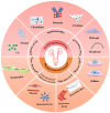
Image 1
Graphical abstract
Fig. 1
Fig. 1
Urinary tract system. Cartoon depicting the organization of the urothelium and underlying tissues in the renal pelvis, ureter, bladder, and proximal urethra. Ut, urothelium, LP, lamina propria; SM, Smooth muscle layers; HSM, Horizontal smooth muscle layers; LSM, Longitudinal smooth muscle layers.
Fig. 2
Fig. 2
Advantages and disadvantages of current in vitro and in vivo models for the urology system.
Fig. 3
Fig. 3
Microfluidic models of cell co-culture with different structures in urinary system. (A) Microfluidic model of a prostate duct. The two PDMS layers are bonded together around a rod allowing creation of a lumen structure molded from a collagen hydrogel (orange). Lumens are lined with benign or metastatic BCaP epithelial cells (purple). PBMCs (green) are added inside the lumen. Media channels allow exchange of cell culture media (pink) from the side channels without perturbing the immune cells in the lumen [58]. Reproduced with permission [58]. Copyright 2020, Royal Society of Chemistry. (B) Proximal tubule on-a-chip model based on membrane. The microfluidic channels overlap to create a filtrate channel (green) in communication with a vascular channel (purple). The cross-sectional architecture (inset) mimics in vivo epithelial-endothelial barrier and generates cell-mediated transport through the membrane [52]. Reproduced with permission [52]. Copyright 2017, Public Library of Science. (C) A reconfigurable multilayer suspended microfluidic system. Layers can be vertically assembled into stacks using a holder (blue). The bottom layer containing a mixed culture of endothelial cells and fibroblasts is removed from the stack, and immunocytochemistry for the endothelial marker CD31 (green) and DAPI staining (blue) is performed to visualize endothelial structures [67]. Reproduced with permission [67]. Copyright 2019, Springer Nature. (D) Schematic illustrations of (a) microextrusion, (b) inkjet, (c) laser-assisted printing, and (d) stereolithography techniques [141]. Reproduced under terms of the CC-BY license [141]. Copyright 2016, American Chemical Society.
Fig. 4
Fig. 4
A microfluidic model for simulating the biochemical microenvironment of urinary system. (A) The distinctive microenvironments of tumors. The multiple stromal cell types create a succession of tumor microenvironments that change as tumors invade normal tissue and thereafter seed and colonize distant tissues. The abundance, histologic organization, and phenotypic characteristics of the stromal cell types, as well as of the ECM (hatched background), evolve during progression, thereby enabling primary, invasive, and then metastatic growth [68]. Reproduced with permission [68]. Copyright 2011, Cell Press. (B) Kidney-on-a-chip is developed for monitoring nephrotoxicity. Schematic design and actual image of a kidney-on-a-chip. Junctional protein expression of each group. The static and shear groups are measured before exposure to gentamicin. All groups show improved polarization compared to Transwell cultures [112]. Reproduced with permission [112]. Copyright 2016, IOP Publishing Ltd.
Fig. 5
Fig. 5
A microfluidic model for simulating the physical microenvironment of urinary system. (A) Glomerulus-on-a-chip microfluidic: podocytes and endothelial cells are cultured on opposite sides of an artificial membrane. Endothelial cells are also affected by blood flow shear force. This chip device can recreate capillary pressure by supplying perfusion flow in the upper microchannel and introducing mechanical forces [137]. Reproduced with permission [137]. Copyright 2022, Springer Nature. (B) A pathological glomerular microenvironment was established by perfusion flow regulating mechanical forces [81]. Reproduced under terms of the CC-BY license [81]. Copyright 2016, Springer Nature. (C) Modelling the human glomerular capillary wall with an organ-on-a-chip microfluidic device. Arrow shows directional flow of molecules from the capillary lumen to urinary space. Cyclic mechanical strain was applied to cell layers by stretching the flexible PDMS membrane using vacuum [82]. Reproduced with permission [82]. Copyright 2017, Springer Nature. (D) Human Bladder-chip model of UTI recapitulates the physiology of bladder filling and voiding. Human bladder epithelial cell line (epithelium, top) and primary human bladder microvascular endothelial cells (endothelial, bottom) on either side of the stretchable and porous membrane. Pooled human urine diluted in PBS and endothelial cell medium were perfused in the apical and vascular channels respectively to mimic bladder physiology. A negative pressure in the ‘vacuum’ channels (magenta) on either side of the main channel was applied to stretch the porous membrane to mimic stretching of the bladder [83]. Reproduced under terms of the CC-BY license [83]. Copyright 2021, eLife Sciences Publications.
Fig. 6
Fig. 6
Disease and high-throughput drug screening-on-chips in urinary system. (A) Schematic of renal hypoxia-reperfusion injury-on-chip model [102]. Reproduced with permission [102]. Copyright 2022, American Chemical Society; (B) Construction of an integrated functional tubule-vascular microfluidic chip. (a) An illustration of the characteristic physiological structures of the renal interstitial microenvironment. (b) Schematic image of a microfluidic renal interstitium-on-a-chip device with microchannels replicating the renal tubules and peritubular microvessels. (c) Photograph of the microfluidic chip (left), and the representative image of the co-culture of HK-2 ​cells, HUVECs, and pericytes in the chip (right) [103]. Reproduced with permission [103]. Copyright 2022, Elsevier BV; (C) Demonstration of concentration gradient in microfl uidic system using color dye solution (a) Trapping of 8 different concentration gradient of a sensitizer through a diffusive mixer by driven micropump from two reservoirs (sensitizer and medium are represented by red and yellow respectively) (b) The second trapping of 8 different concentration gradient of drug (drug was represented by blue color dye) (c) Concentration gradient of color dye was maintained 4 ​h after closing valves without perfusion of reagent (d) Representative cell culture chamber with PC3 cells trapped and grown for 24 ​h [118]. Reproduced under terms of the CC-BY license [118]. Copyright 2014, Korean Society of Applied Pharmacology; (D) Microfluidic device layout and functions. (a) Schematic representation of the device structure. (b) Fluorescent image showing a calcein concentration gradient over the micro-well array. (c) Schematic cross-section of the gradient generated along a column of the spheroid array [119]. Reproduced under terms of the CC-BY license [119]. Copyright 2018, Springer Nature; (E) The human proximal renal tubule-on-chip for the study of nephrotoxicity and drug interaction. (a) Image of the back side of the OrganoPlate 3-lane. The microfluid network is positioned in-between a glass sandwich of two microscope grade glass plates which are attached to the bottom of a standard 384 titer well plate. (b) Schematic of one chip presenting two perfusion channels and the extracellular matrix (ECM) channel in the middle. (c) Artist impression of one chip. The chip was loaded with collagen 1 (blue) to the ECM channel and proximal tubule cells (yellow) were seeded to the top channel [117]. Reproduced under terms of the CC-BY license [117]. Copyright 2021, Elsevier.
Fig. 7
Fig. 7
Challenges, development and future directions in urinary system microfluidic models. (A) The challenge of microfluidic technology in simulating real microenvironment lies in the lack of physiological parameters, including urine flow velocity, stiffness of ECM, porosity and so on. (B) The urinary system microfluidic model has developed from a single channel to an integrated, high-throughput channel, and the practicability and standardization are increasing, and the connotation of its microenvironment is also being enriched. (C) With the further study of pathophysiology of urinary system, the improvement of chip structure design and fabrication process, and multi-parameter microenvironment simulation and control will help to promote the development of urinary system microfluidic models.

Similar articles

Cited by

References

    1. Jones-Freeman B., Chonwerawong M., Marcelino V.R., Deshpande A.V., Forster S.C., Mr S. The microbiome and host mucosal interactions in urinary tract diseases. Mucosal Immunol. 2021;14(4):779–792. - PubMed
    1. Dalghi M.G., Montalbetti N., Carattino M.D., G. A The urothelium: life in a liquid environment. Physiol. Rev. 2020;100:1621–1705. - PMC - PubMed
    1. Wa rrick J.W., Murphy W.L., B.b. DJ Screening the cellular microenvironment: a role for microfluidics. Ieee Reviews In Biomedical Engineering. 2008;1:75∼93. - PMC - PubMed
    1. Ma Y., Li Y., Yang Y., L. P. The microenvironment that regulates vascular wall stem/progenitor cells in vascular injury and repair. BioMed Res. Int. 2022;2022 - PMC - PubMed
    1. Makkar H., Zhou Y., Tan K.S., Lim Ct S.G. Modelling crevicular fluid flow and host-Oral microbiome interactions in a gingival crevice-on-Chip. Adv Healthc Mater. 2022;17 - PubMed

LinkOut - more resources