Review
. 2022 Oct-Dec;13(4):368-377.
doi: 10.4103/jcvjs.jcvjs_128_22. Epub 2022 Dec 7.

C2 Screw fixation techniques in atlantoaxial instability: A technical review

Affiliations
Review

C2 Screw fixation techniques in atlantoaxial instability: A technical review

Deepak Kumar Singh et al. J Craniovertebr Junction Spine. 2022 Oct-Dec.

Abstract

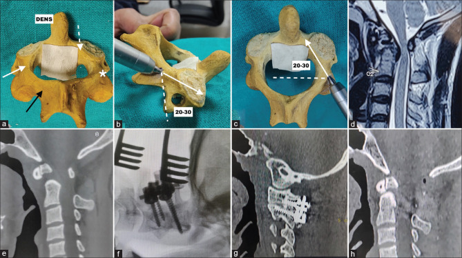
Atlantoaxial instability (AAI) is surgically a complex entity due to its proximity to vital neurovascular structures. C1-C2 fusion has been an established standard in its treatment for a considerable time now. Here, we have outlined the most common techniques for C2 screw fixation in practice at present such as C2 pedicle, C2 pars, C2 translaminar, C2 subfacetal, C2-C3 transfacetal, and C2 inferior facet screw. We have discussed in detail the technical as well as biomechanical aspects of each technique of C2 screw fixation in AAI and explored the intricacies of each technique.

Keywords: AAD; C2 inferior facet; C2 laminar; C2 screws; C2/C3 transfacet; atlantoaxial instability.


Conflict of interest statement

There are no conflicts of interest

Figures

Figure 1
Figure 1
(Pedicle screw) Goel and Laheri and Harms and Melcher[13],[15] technique for C2 (Axis) pedicle screw. (a) Entry point is at the cranial and medial quadrant of the C2 isthmus surface along the superior border of the C2 lamina denoted by the white star. DENS: Dens process of C2; C2 Pars: solid white arrow; C2 Pedicle: Interrupted white arrow; C2 lamina: Solid black arrow. (b) Cranio-caudal angulation on the sagittal plane is 20°–30° cranially. (c) 20°–30° medial angulation on the axial plane denoted by the white arrow parallel to the superomedial surface of the C2 pedicle. (d) T2-weighted MRI craniovertebral junction of a 30-year-old male presenting with spastic quadriparesis showing atlantoaxial instability and cord compression with myelomalacia changes in the cord. (e) Preoperative CT scan of the patient with mid-sagittal cuts showing Type 2 odontoid fracture with AAI. (f) Intraoperative C-arm X-ray image showing placement of bilateral C1 lateral mass and C2 pedicle screws. (g) Postoperative CT scan with sagittal cuts passing through right C1-C2 facet joint showing C1 lateral mass screw and C2 pedicle screw with rods and bone graft in joint space. (h) Postoperative CT scan with mid-sagittal cut showing opened-up canal space after reduction. MRI - Magnetic resonance imaging; CT - Computer tomography
Figure 2
Figure 2
(Pars screw) Technique for C2 (Axis) pars screw. (a) Entry point is 2–3 mm superior and lateral to the medial aspect of the C2-C3 facet joint denoted by the white star. (b) Cranio-caudal angulation on the sagittal plane is at 45° cranially along the C2-3 facet denoted by the white arrow. (c) 10° medial angulation on the axial plane denoted by the white arrow towards the anterior tubercle of C1. (d) T2-weighted MRI craniovertebral junction of a 38-year-old male presenting with difficulty in walking showing atlantoaxial instability with basilar invagination and myelomalacia changes in the spinal cord. (e) Preoperative CT scan of the patient with mid-sagittal cuts showing atlantoaxial instability with basilar invagination. (f) Preoperative CT scan with axial cuts passing through bilateral C2 pedicles showing thin right C2 pedicle (shown with white arrow) for which pars screw placement was done. (g) Intraoperative C-arm X-ray image showing placement of bilateral C1 lateral mass with right C2 pars screw and left C2 pedicle screw. (h) Postoperative CT scan with mid-sagittal cut showing reduction of basilar invagination and AAD. C1: Atlas vertebra. MRI - Magnetic resonance imaging; CT - Computer tomography
Figure 3
Figure 3
(Translaminar) Wrights[16] technique for C2 (Axis) translaminar screw. (a) Entry point is at the junction of the C2 spinous process and lamina on the right, close to the rostral margin of the C2 lamina denoted by the white star. Similarly, at the junction of the spinous process and lamina of C2 on the left, close to the caudal aspect of the lamina is denoted by another white star. Direction is along the angle of the exposed contralateral C2 laminar surface and Parallel to the rostral margins of the C2 lamina denoted by the white arrow. (b) Placement of bilateral translaminar screws on a saw bone model of the C2 vertebra. (c) T2-weighted MRI craniovertebral junction of a 40-year-old female presenting with neck pain and difficulty in walking showing atlantoaxial instability with basilar invagination and cord compression. (d) Preoperative CT scan of the patient with mid-sagittal cut showing atlantoaxial instability with basilar invagination. (e) Axial CT scan image of C2 vertebra through bilateral pedicle showing thin right pedicle making pedicle screw difficult on this side. (f) Intraoperative C-arm X-ray image showing placement of bilateral C1 lateral mass with right C2 translaminar screw and left C2 pedicle screw. (g) Postoperative CT scan with mid-sagittal cut showing significant reduction of basilar invagination and AAD. (h) Postoperative computer CT scan with axial cut passing through C2 lamina showing right C2 translaminar screw with the rod. MRI - Magnetic resonance imaging; CT - Computer tomography
Figure 4
Figure 4
Technique for C2 (Axis) subfacetal screw.[36] (a) Entry point is at 3 mm–4 mm below the mid-point of the upper surface of the C2 superior facet with 20° medial angulation on the axial plane denoted by the white arrow. (b) Cranio-caudal angulation on the sagittal plane is variable usually put 10° caudally denoted by the white arrow. (c) T2-weighted magnetic resonance imaging (MRI) craniovertebral junction of a 67-year-old female presenting with neck pain and difficulty in walking showing atlantoaxial instability with cord com-pression and myelomalacia changes in the cord. (d) Preoperative CT scan of the patient with mid-sagittal cut showing atlantoaxial instability with severe canal compromise. (e) Axial CT scan image of C2 vertebra through bilateral pedicle showing thin left pedicle making pedicle screw difficult on both sides. (f) Intraoperative C-arm X-ray image showing placement of bi-lateral C1 lateral mass with bilateral C2 subfacetal screw. (g) Postoperative CT scan with sag-ittal cut passing through left C1-C2 facet joint showing C1 lateral mass screw and C2 sub-facetal screw with the rod. (h) Postoperative CT scan with mid-sagittal cuts showing reduction of AAI and opening of the canal. CT - Computer tomography; AAI - Atlantoaxial instability
Figure 5
Figure 5
(Transfacet) Goel's[17] technique for C2 (Axis) transfacet screw. (a) Entry point is 5mm above the middle of the C2-C3 facet joint denoted by the white star. (b) 0° medial angulation on axial and coronal planes denoted by the white arrow. (c) Cranio-caudal angulation on the sagittal plane is 45° caudally, perpendicular to the C2-C3 facet joints denoted by the white arrow. (d) T2-weighted MRI craniovertebral junction of a 37-year-old male presenting with neck pain and spastic quadriparesis showing atlantoaxial instability and cord compression with myelomalacia changes in the cord. (e) Preoperative CT scan of the patient with mid-sagittal cut showing AAI with a compromised canal. (f) Intraoperative C-arm X-ray image showing placement of bilateral C1 lateral mass with right C2-C3 transfacet screw and left C2 pedicle screw. (g) Postoperative CT scan with sagittal cut passing through right C1-C2-C3 facet joints showing C1 lateral mass screw and C2-C3 transfacet screw with the rod. A very thin C2 pedicle is also noted. (h) Postoperative CT scan with mid-sagittal cuts showing opened-up canal space after reduction. MRI - Magnetic resonance imaging; CT - Computer tomography
Figure 6
Figure 6
(inferior facet) Goel's[17] technique for C2 (Axis) inferior facet screw. (a) Entry point is at the medial aspect of the lamina at its junction with the pedicle denoted by the white star. (b) Cranio-caudal angulation on the sagittal plane is 45° caudally denoted by the white arrow. (c) 20° lateral angulation on the coronal plane denoted by the white arrow. (d) T2-weighted MRI craniovertebral junction of a 33-year-old male presenting with spastic quadriparesis showing atlantoaxial instability, Chiari malfor-mation, and syringomyelia. (e) Axial CT image of C2 vertebra through bilateral pedicle showing thin right pedicle (white arrow) making pedicle screw insertion difficult on this side. (f) Intraoperative C-arm X-ray image showing placement of bilateral C1 lateral mass with right C2 inferior facet screw and left C2 pedicle screw. (g) Postoperative CT scan with sagittal cut passing through right C1-C2 facet joints showing C1 lateral mass screw and C2 inferior facet screw with the rod. (h) Postoperative CT scan with mid-sagittal cut showing opened-up canal space after reduction and posterior fossa decompression. MRI - Magnetic resonance imaging; CT - Computer tomography

References

    1. Mummaneni PV, Haid RW. Atlantoaxial fixation: Overview of all techniques. Neurol India. 2005;53:408–15. - PubMed
    1. Du JY, Aichmair A, Kueper J, Wright T, Lebl DR. Biomechanical analysis of screw constructs for atlantoaxial fixation in cadavers: A systematic review and meta-analysis. J Neurosurg Spine. 2015;22:151–61. - PubMed
    1. Jeanneret B, Magerl F. Primary posterior fusion C1/2 in odontoid fractures: Indications, technique, and results of transarticular screw fixation. J Spinal Disord. 1992;5:464–75. - PubMed
    1. Panjabi MM, Duranceau J, Goel V, Oxland T, Takata K. Cervical human vertebrae-quantitative three dimentional anatomy of the middle and lower regions. Spine (Phila Pa 1976) 1991;16:861–9. - PubMed
    1. Xu R, Nadaud MC, Ebraheim NA, Yeasting RA. Morphology of the second cervical vertebra and the posterior projection of the C2 pedicle axis. Spine (Phila Pa 1976) 1995;20:259–63. - PubMed