This is a preprint.
An implantable wireless tactile sensing system
- PMID: 36778258
- PMCID: PMC9915765
- DOI: 10.21203/rs.3.rs-2515082/v1
An implantable wireless tactile sensing system
Update in
-
An implantable, wireless, battery-free system for tactile pressure sensing.Microsyst Nanoeng. 2023 Oct 11;9:130. doi: 10.1038/s41378-023-00602-3. eCollection 2023. Microsyst Nanoeng. 2023. PMID: 37829157 Free PMC article.
Abstract
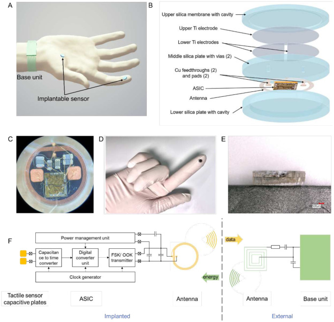
The sense of touch is critical to dexterous use of the hands and thus an essential component to efforts to restore hand function after amputation or paralysis. Prosthetic systems have focused on wearable tactile sensors. But wearable sensors are suboptimal for neuroprosthetic systems designed to reanimate a patient's own paralyzed hand. Here, we developed an implantable tactile sensing system intended for subdermal placement. The system is composed of a microfabricated capacitive force sensor, a custom integrated circuit supporting wireless powering and data transmission, and a laser-fused hermetic silica package. The miniature device was validated through simulations, benchtop testing, and ex vivo testing in a primate hand. The sensor implanted in the fingertip accurately measured skin forces with a resolution of 4.3 mN. The output from this novel sensor could be encoded in the brain with microstimulation to provide tactile feedback. More broadly, the materials, system design, and fabrication approach establish new foundational capabilities for various applications of implantable sensing systems.
Conflict of interest statement
Conflict of interests The authors declare that they have no competing interests.
Figures


References
-
- Boutry C.M., et al. , “A hierarchically patterned, bioinspired e-skin able to detect the direction of applied pressure for robotics,” Science Robotics, 3(24), p.eaau6914, 2018. - PubMed
-
- Liang G., Wang Y., Mei D., Xi K., and Chen Z., “Flexible capacitive tactile sensor array with truncated pyramids as dielectric layer for three-axis force measurement,” Journal of Microelectromechanical Systems, vol. 24, no. 5, pp. 1510–1519, 2015.
-
- Liang G., Wang Y., Mei D., Xi K., and Chen Z., “An analytical model for studying the structural effects and optimization of a capacitive tactile sensor array,” Journal of Micromechanics and Microengineering, vol. 26, no. 4, p. 045007, 2016.
-
- Woo S. J., Kong J. H., Kim D. G., and Kim J. M., “A thin all-elastomeric capacitive pressure sensor array based on micro-contact printed elastic conductors,” Journal of Materials Chemistry C, vol. 2, no. 22, pp. 4415–4422, 2014.
Publication types
Grants and funding
LinkOut - more resources
Full Text Sources