. 2023 Feb 17;14(1):912.
doi: 10.1038/s41467-023-36493-1.

Fusion-based quantum computation

Affiliations

Fusion-based quantum computation

Sara Bartolucci et al. Nat Commun. .

Abstract

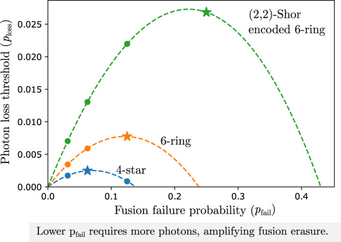
The standard primitives of quantum computing include deterministic unitary entangling gates, which are not natural operations in many systems including photonics. Here, we present fusion-based quantum computation, a model for fault tolerant quantum computing constructed from physical primitives readily accessible in photonic systems. These are entangling measurements, called fusions, which are performed on the qubits of small constant sized entangled resource states. Probabilistic photonic gates as well as errors are directly dealt with by the quantum error correction protocol. We show that this computational model can achieve a higher threshold than schemes reported in literature. We present a ballistic scheme which can tolerate a 10.4% probability of suffering photon loss in each fusion, which corresponds to a 2.7% probability of loss of each individual photon. The architecture is also highly modular and has reduced classical processing requirements compared to previous photonic quantum computing architectures.


Conflict of interest statement

The authors declare no competing interests

Figures

Fig. 1
Fig. 1. An example fusion network and schematic of a fusion based quantum computing architecture.
a A 2D example of a fusion network, where entangled resource states and fusions are structured as a regular 2D square lattice. Resource states (1) are graph states made up of four entangled qubits in a square configuration. (2) These qubits are measured pairwise in entangling fusion measurements as depicted by the grey shaded ovals. b An example architecture which could create the fusion network shown in a. Each qubit is created in a resource state generator (1) and traverses the architecture from left to right through stages labelled 2–6. Qubits are connected to fusions (4) via a fusion network router (2), which can include time delays (3). Fusion devices may be reconfigurable such that they can make projective measurements in different bases. Classical signals from fusion measurements (5) are fed to a classical processor (6), which is responsible for decoding and algorithmic logic. There can be feedforward from this computation to reconfigure fusion measurements in order to implement logic. This figure illustrates how the fusion network may include one (or more) additional dimensions compared to the hardware. Here the fusion network is 2D and the physical hardware is a 1D array of resource state generation and fusion. The physical architecture for fault tolerant computing is discussed further in section 0.6.
Fig. 2
Fig. 2. The “6-ring” fusion network.
a Each resource state is a graph state in the form of a ring of 6 qubits. Two resource states are placed at opposite corners of each unit cell. b 2 qubit fusions connect every pair of qubits that share a face or an edge. Resource states that belong to the unit cell are shown as purple circles, while qubits from resource states in neighboring cells are shown as white circles. A formal definition of the fusion network can be found in Supplementary note VB. c All fusion measurements in the fusion network are two qubit projective measurements projective measurements on the bases M1 = X1X2 and M2 = Z1Z2. d Shows the layout of resource states across multiple unit cells. When unit cells are tiled, the resource states can be grouped into layers along 2D planes perpendicular to the (1,1,1) direction. Three qubits in each state fuse with the layer above, and three with the layer below. e The syndrome graph resulting from the fusion layout is a cubic graph with diagonal edges as shown. Primal and dual syndrome graphs have an identical structure. In both, the vertical edges correspond to XX type fusion outcomes and diagonal edges correspond to ZZ outcomes. The unit cells for primal and dual syndrome graphs can be interpreted as shifted by (1/2,1/2,1/2) so that each fusion corresponds to both a primal and dual edge which cross perpendicularly at the location of the fusion itself.
Fig. 3
Fig. 3. Performance of the six-ring (orange line) and 4-star (blue line, FBQC version of best architecture in literature, see Supplementary note VA) fusion networks.
The correctable region is shown for the two fusion networks under the two error parameters of the hardware-agnostic fusion error model: fusion erasure probability perasure and measurement error probability perror. Each marker shows the position of the threshold in the 2 parameter space, and is evaluated by a series of Montecarlo error sampling and decoding trials at different error parameters. Simulation details are provided in Supplementary note VII.
Fig. 4
Fig. 4. Photon loss threshold for the three fusion networks: 4-star (blue) and 6-ring (orange) and (2,2)-Shor encoded 6-ring (green).
The threshold is calculated under the linear optical error model with the same photon loss probability ploss applied to every photon in the protocol. We consider a physical model for fusion failure where pfail = 1/2n can be achieved by boosting a fusion with 2n − 2 additional photons. Since more photons are required for these lower fusion failure rates, the effect of loss in this regime is amplified, with a probability (1ploss)2n of no photon in the fusion being lost. Because of this the protocols demonstrate an optimal performance at some intermediate value of pfail. The markers represent the values of pfail that can be achieved with fusions and the stars represent the optimum levels of boosting for the different schemes. The green curve corresponds to the 6-ring fusion network with qubits encoded in a (2,2)-Shor code. The details of the encoding and measurement scheme, and the error model used to evaluate these curves is explained in Supplementary note IIB and IIC.
Fig. 5
Fig. 5. A scheme for creating boundaries that can be used to modify the bulk to perform quantum computation.
Boundaries are classified as “primal” if they are “rough'' ("smooth'') for the primal (dual) syndrome graphs, and are classified as “dual” if they are “rough'' ("smooth'') for the dual (primal) syndrome graphs. a, b show modified unit cells of a fusion network that can generate a primal and dual boundary respectively. In each, the fusion network is made up of the same configuration of resource states as in the bulk (see Fig. 2), but where some subset of the fusion measurements have been replaced with single qubit Z measurements, and some subset of the resource states are entirely removed (indicated by greyed out circles). If at the boundary a resource state has no remaining entangling operations connecting it into the bulk, then it does not need to be created. All the remaining fusions (shown by orange ovals) are a projective measurement on XX, and ZZ. The effect of this modified network is to truncate the bulk either at (a) a slice halfway through the cell or (b) at the edge of the cell. c shows an example of hows these unit cells can be composed to create macroscopic boundary conditions, enabling fault-tolerant logic. It corresponds to the initialization of a standard surface code in the computational basis.
Fig. 6
Fig. 6. Example of a physical layout of resource state generators and fusion routing that can be used to create the 6-ring fusion network.
a Four RSGs are shown, each producing a 6-ring state in each clock cycle. These are arranged in a tileable configuration. Qubits from each RSG are routed to 2-qubit fusion devices. b Each fusion device can include a switch that can reconfigure between multiple fusion settings to implement logical gates. Each RSG outputs 6 qubits per clock cycle. c Four qubits from each state immediately enter a fusion device in one of the four spatial directions: North, South, East or West. This generates entanglement between states created at neighboring sites in the same time step. d The two remaining qubits from each state are used to generate entanglement between states produced at the same physical location, but in different time steps. To achieve this, one qubit passes through a 1 clock cycle delay, so that it arrives at the fusion device coincidentally with a state produced in the following clock cycle. Fusion measurement outcomes are output from the system as classical data. In the bulk no data input is required, but classical control is needed at certain locations to reconfigure fusion devices to perform logical gates.

References

    1. Raussendorf R, Briegel HJ. A one-way quantum computer. Phys. Rev. Lett. 2001;86:5188. doi: 10.1103/PhysRevLett.86.5188. - DOI - PubMed
    1. Knill E, Laflamme R, Milburn GJ. A scheme for efficient quantum computation with linear optics. Nature. 2001;409:46–52. doi: 10.1038/35051009. - DOI - PubMed
    1. Browne DE, Rudolph T. Resource-efficient linear optical quantum computation. Phys. Rev. Lett. 2005;95:010501. doi: 10.1103/PhysRevLett.95.010501. - DOI - PubMed
    1. Nielsen MA. Optical quantum computation using cluster states. Phys. Rev. Lett. 2004;93:040503. doi: 10.1103/PhysRevLett.93.040503. - DOI - PubMed
    1. Raussendorf R, Harrington J. Fault-tolerant quantum computation with high threshold in two dimensions. Phys. Rev. Lett. 2007;98:190504. doi: 10.1103/PhysRevLett.98.190504. - DOI - PubMed