Bulk Rashba-Type Spin Splitting in Non-Centrosymmetric Artificial Superlattices
- PMID: 36808490
- PMCID: PMC10131871
- DOI: 10.1002/advs.202206800
Bulk Rashba-Type Spin Splitting in Non-Centrosymmetric Artificial Superlattices
Abstract
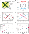
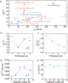
Spin current, converted from charge current via spin Hall or Rashba effects, can transfer its angular momentum to local moments in a ferromagnetic layer. In this regard, the high charge-to-spin conversion efficiency is required for magnetization manipulation for developing future memory or logic devices including magnetic random-access memory. Here, the bulk Rashba-type charge-to-spin conversion is demonstrated in an artificial superlattice without centrosymmetry. The charge-to-spin conversion in [Pt/Co/W] superlattice with sub-nm scale thickness shows strong W thickness dependence. When the W thickness becomes 0.6 nm, the observed field-like torque efficiency is about 0.6, which is an order larger than other metallic heterostructures. First-principles calculation suggests that such large field-like torque arises from bulk-type Rashba effect due to the vertically broken inversion symmetry inherent from W layers. The result implies that the spin splitting in a band of such an ABC-type artificial SL can be an additional degree of freedom for the large charge-to-spin conversion.
Keywords: artificial superlattice; bulk Rashba-type spin splitting; charge-to-spin conversion; spin current.
© 2023 The Authors. Advanced Science published by Wiley-VCH GmbH.
Conflict of interest statement
The authors declare no conflict of interest.
Figures


References
-
- Manipatruni S., Nikonov D. E., Lin C.‐C., Gosavi T. A., Liu H., Prasad B., Huang Y.‐L., Bonturim E., Ramesh R., Young I. A., Nature 2019, 565, 35. - PubMed
-
- Ralph D. C., Stiles M. D., J. Magn. Magn. Mater. 2008, 320, 1190.
-
- Manchon A., Železný J., Miron I. M., Jungwirth T., Sinova J., Thiaville A., Garello K., Gambardella P., Rev. Mod. Phys. 2019, 91, 035004.
-
- Mihai Miron I., Gaudin G., Auffret S., Rodmacq B., Schuhl A., Pizzini S., Vogel J., Gambardella P., Nat. Mater. 2010, 9, 230. - PubMed
-
- Liu L., Pai C.‐F., Li Y., Tseng H. W., Ralph D. C., Buhrman R. A., Science 2012, 336, 555. - PubMed
Grants and funding
- JP26103002/JSPS KAKENHI
- JP26870300/JSPS KAKENHI
- JP17H05181/JSPS KAKENHI
- JP17J07666/JSPS KAKENHI
- NRF-2018R1A4A1020696/National Research Foundation of Korea
- NRF-2019R1C1C1010345/National Research Foundation of Korea
- NRF-2019R1A6A1A11053838/National Research Foundation of Korea
- NRF-2019R1I1A3A01059880/National Research Foundation of Korea
- SRFC/Samsung Research Funding Center of Samsung Electronics
- IT1901/Samsung Research Funding Center of Samsung Electronics
- 11/Samsung Research Funding Center of Samsung Electronics
- 2017B0924/Samsung Research Funding Center of Samsung Electronics
- KIST Institutional Programs
