

Ionothermal Synthesis of Metal-Organic Frameworks Using Low-Melting Metal Salt Precursors
- PMID: 36811601
- PMCID: PMC10079605
- DOI: 10.1002/anie.202218252
Ionothermal Synthesis of Metal-Organic Frameworks Using Low-Melting Metal Salt Precursors
Abstract
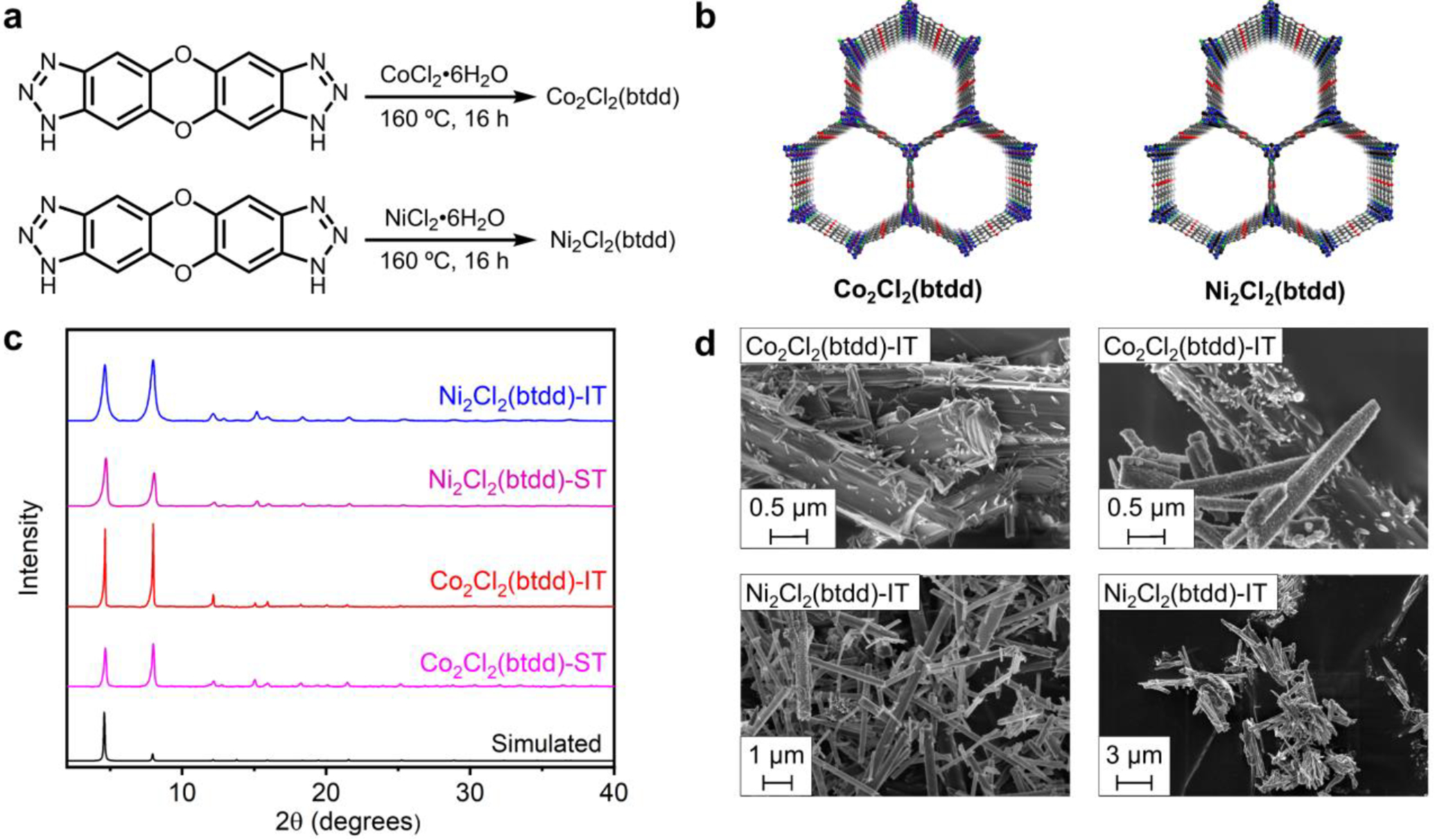
Metal-organic frameworks (MOFs) are porous, crystalline materials constructed from organic linkers and inorganic nodes with myriad potential applications in chemical separations, catalysis, and drug delivery. A major barrier to the application of MOFs is their poor scalability, as most frameworks are prepared under highly dilute solvothermal conditions using toxic organic solvents. Herein, we demonstrate that combining a range of linkers with low-melting metal halide (hydrate) salts leads directly to high-quality MOFs without added solvent. Frameworks prepared under these ionothermal conditions possess porosities comparable to those prepared under traditional solvothermal conditions. In addition, we report the ionothermal syntheses of two frameworks that cannot be prepared directly under solvothermal conditions. Overall, the user-friendly method reported herein should be broadly applicable to the discovery and synthesis of stable metal-organic materials.
Keywords: Conductivity; Ionothermal; Metal-Organic Framework; Porosity; Sustainability.
© 2023 Wiley-VCH GmbH.
Figures


Similar articles
-
Simplifying the Synthesis of Metal-Organic Frameworks.Acc Mater Res. 2023 Oct 27;4(10):867-878. doi: 10.1021/accountsmr.3c00121. Epub 2023 Oct 3. Acc Mater Res. 2023. PMID: 38226178 Free PMC article.
-
High-Concentration Self-Assembly of Zirconium- and Hafnium-Based Metal-Organic Materials.J Am Chem Soc. 2023 Jun 21;145(24):13273-13283. doi: 10.1021/jacs.3c02787. Epub 2023 Jun 9. J Am Chem Soc. 2023. PMID: 37294975 Free PMC article.
-
Postsynthetic Tuning of Metal-Organic Frameworks for Targeted Applications.Acc Chem Res. 2017 Apr 18;50(4):805-813. doi: 10.1021/acs.accounts.6b00577. Epub 2017 Feb 8. Acc Chem Res. 2017. PMID: 28177217
-
The Synthesis and Properties of TIPA-Dominated Porous Metal-Organic Frameworks.Nanomaterials (Basel). 2021 Oct 21;11(11):2791. doi: 10.3390/nano11112791. Nanomaterials (Basel). 2021. PMID: 34835554 Free PMC article. Review.
-
Structure-directing effects of ionic liquids in the ionothermal synthesis of metal-organic frameworks.IUCrJ. 2017 Jun 30;4(Pt 4):380-392. doi: 10.1107/S2052252517008326. eCollection 2017 Jul 1. IUCrJ. 2017. PMID: 28875025 Free PMC article. Review.
Cited by
-
Simplifying the Synthesis of Metal-Organic Frameworks.Acc Mater Res. 2023 Oct 27;4(10):867-878. doi: 10.1021/accountsmr.3c00121. Epub 2023 Oct 3. Acc Mater Res. 2023. PMID: 38226178 Free PMC article.
-
Validation and Mechanistic Studies of the Headspace Effect in MOF Synthesis.Angew Chem Int Ed Engl. 2025 Mar 17;64(12):e202500531. doi: 10.1002/anie.202500531. Epub 2025 Feb 14. Angew Chem Int Ed Engl. 2025. PMID: 39899272 Free PMC article.
-
Cobalt(III) Halide Metal-Organic Frameworks Drive Catalytic Halogen Exchange.J Am Chem Soc. 2024 Apr 12:10.1021/jacs.3c13872. doi: 10.1021/jacs.3c13872. Online ahead of print. J Am Chem Soc. 2024. PMID: 38607314
-
Solvent-free construction of Cr(iii)-sulfonate coordination polymers.Chem Sci. 2025 May 31;16(26):11823-11832. doi: 10.1039/d5sc03014e. eCollection 2025 Jul 2. Chem Sci. 2025. PMID: 40496503 Free PMC article.
-
MOFganic Chemistry: Challenges and Opportunities for Metal-Organic Frameworks in Synthetic Organic Chemistry.Chem Mater. 2023 Jul 11;35(13):4883-4896. doi: 10.1021/acs.chemmater.3c00741. Epub 2023 Jun 21. Chem Mater. 2023. PMID: 38222037 Free PMC article.
References
Grants and funding
LinkOut - more resources
Full Text Sources
