

The complex structure of Fomes fomentarius represents an architectural design for high-performance ultralightweight materials
- PMID: 36812306
- PMCID: PMC9946349
- DOI: 10.1126/sciadv.ade5417
The complex structure of Fomes fomentarius represents an architectural design for high-performance ultralightweight materials
Abstract
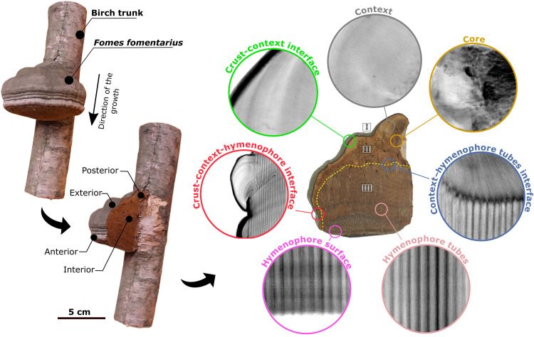
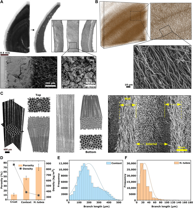
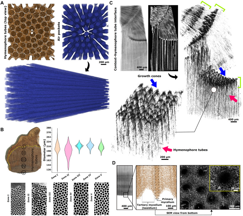
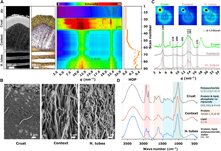
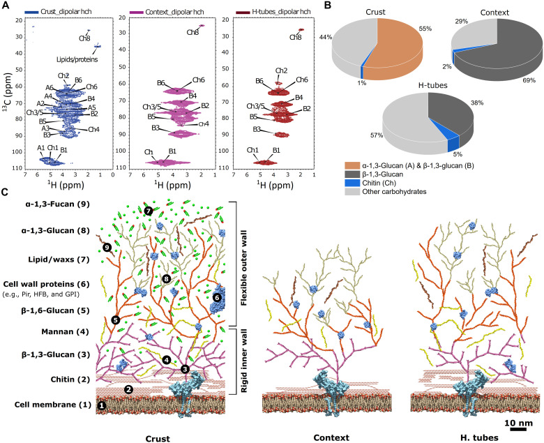
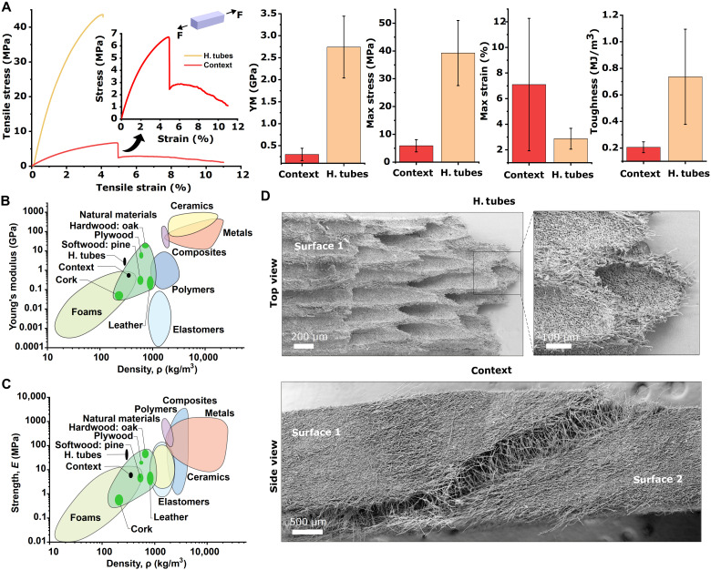
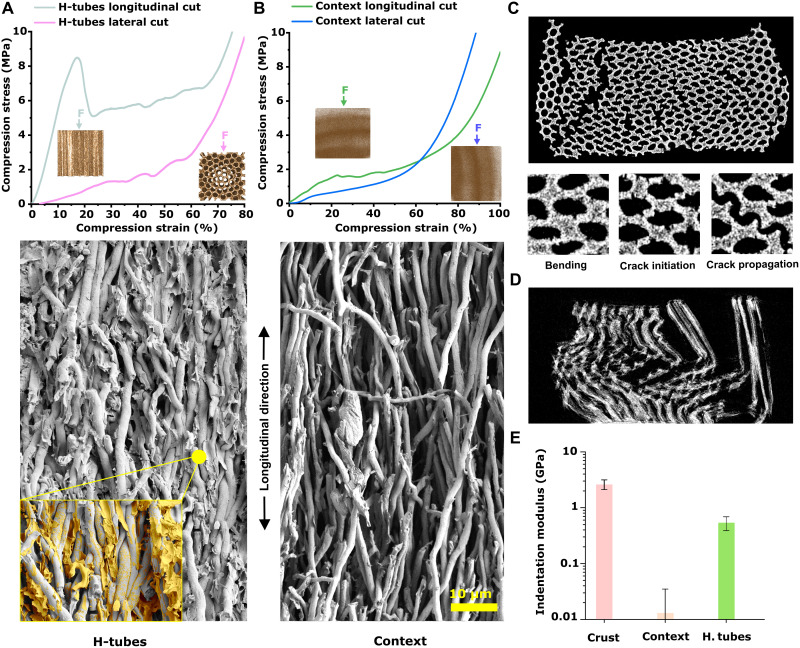
High strength, hardness, and fracture toughness are mechanical properties that are not commonly associated with the fleshy body of a fungus. Here, we show with detailed structural, chemical, and mechanical characterization that Fomes fomentarius is an exception, and its architectural design is a source of inspiration for an emerging class of ultralightweight high-performance materials. Our findings reveal that F. fomentarius is a functionally graded material with three distinct layers that undergo multiscale hierarchical self-assembly. Mycelium is the primary component in all layers. However, in each layer, mycelium exhibits a very distinct microstructure with unique preferential orientation, aspect ratio, density, and branch length. We also show that an extracellular matrix acts as a reinforcing adhesive that differs in each layer in terms of quantity, polymeric content, and interconnectivity. These findings demonstrate how the synergistic interplay of the aforementioned features results in distinct mechanical properties for each layer.
Figures
Similar articles
-
Mechanical, physical and thermal properties of composite materials produced with the basidiomycete Fomes fomentarius.Fungal Biol Biotechnol. 2023 Dec 4;10(1):22. doi: 10.1186/s40694-023-00169-8. Fungal Biol Biotechnol. 2023. PMID: 38049892 Free PMC article.
-
Hierarchical structure and chemical composition of complementary segments of the fruiting bodies of Fomes fomentarius fungi fine-tune the compressive properties.PLoS One. 2024 Jun 13;19(6):e0304614. doi: 10.1371/journal.pone.0304614. eCollection 2024. PLoS One. 2024. PMID: 38870218 Free PMC article.
-
Establishment of the basidiomycete Fomes fomentarius for the production of composite materials.Fungal Biol Biotechnol. 2022 Feb 24;9(1):4. doi: 10.1186/s40694-022-00133-y. Fungal Biol Biotechnol. 2022. PMID: 35209941 Free PMC article.
-
Medicinal Value and Taxonomy of the Tinder Polypore, Fomes fomentarius (Agaricomycetes): A Review.Int J Med Mushrooms. 2016;18(10):851-859. doi: 10.1615/intjmedmushrooms.v18.i10.10. Int J Med Mushrooms. 2016. PMID: 27910753 Review.
-
Medicinal Potential of the Insoluble Extracted Fibers Isolated from the Fomes fomentarius (Agaricomycetes) Fruiting Bodies: A Review.Int J Med Mushrooms. 2023;25(3):21-35. doi: 10.1615/IntJMedMushrooms.2022047222. Int J Med Mushrooms. 2023. PMID: 37017659 Review.
Cited by
-
Mechanical, physical and thermal properties of composite materials produced with the basidiomycete Fomes fomentarius.Fungal Biol Biotechnol. 2023 Dec 4;10(1):22. doi: 10.1186/s40694-023-00169-8. Fungal Biol Biotechnol. 2023. PMID: 38049892 Free PMC article.
-
Decomposition of Fomes fomentatius fruiting bodies - transition of healthy living fungus into a decayed bacteria-rich habitat is primarily driven by Arthropoda.FEMS Microbiol Ecol. 2024 Apr 10;100(5):fiae044. doi: 10.1093/femsec/fiae044. FEMS Microbiol Ecol. 2024. PMID: 38640440 Free PMC article.
-
Antibacterial Efficacy and Characterization of Silver Nanoparticles Synthesized via Methanolic Extract of Fomes fomentarius L. Fr.Molecules. 2024 Aug 22;29(16):3961. doi: 10.3390/molecules29163961. Molecules. 2024. PMID: 39203038 Free PMC article.
-
Hierarchical structure and chemical composition of complementary segments of the fruiting bodies of Fomes fomentarius fungi fine-tune the compressive properties.PLoS One. 2024 Jun 13;19(6):e0304614. doi: 10.1371/journal.pone.0304614. eCollection 2024. PLoS One. 2024. PMID: 38870218 Free PMC article.
-
From Nature to Design: Tailoring Pure Mycelial Materials for the Needs of Tomorrow.J Fungi (Basel). 2024 Feb 28;10(3):183. doi: 10.3390/jof10030183. J Fungi (Basel). 2024. PMID: 38535193 Free PMC article. Review.
References
-
- Z. Liu, Z. Zhang, R. O. Ritchie, On the materials science of nature’s arms race. Adv. Mater. 30, 1705220 (2018). - PubMed
-
- U. G. K. Wegst, H. Bai, E. Saiz, A. P. Tomsia, R. O. Ritchie, Bioinspired structural materials. Nat. Mater. 14, 23–36 (2015). - PubMed
-
- W. Huang, D. Restrepo, J. Jung, F. Y. Su, Z. Liu, R. O. Ritchie, J. McKittrick, P. Zavattieri, D. Kisailus, Multiscale toughening mechanisms in biological materials and bioinspired designs. Adv. Mater. 31, 1901561 (2019). - PubMed
-
- S. E. Naleway, M. M. Porter, J. McKittrick, M. A. Meyers, Structural design elements in biological materials: Application to bioinspiration. Adv. Mater. 27, 5455–5476 (2015). - PubMed
-
- S. Xiao, C. Chen, Q. Xia, Y. Liu, Y. Yao, Q. Chen, M. Hartsfield, A. Brozena, K. Tu, S. J. Eichhorn, Y. Yao, J. Li, W. Gan, S. Q. Shi, V. W. Yang, M. lo Ricco, J. Y. Zhu, I. Burgert, A. Luo, T. Li, L. Hu, Lightweight, strong, moldable wood via cell wall engineering as a sustainable structural material. Science 374, 465–471 (2021). - PubMed
MeSH terms
Supplementary concepts
LinkOut - more resources
Full Text Sources
