Review
. 2023 Jan 28:19:100565.
doi: 10.1016/j.mtbio.2023.100565. eCollection 2023 Apr.

Electronic textiles: New age of wearable technology for healthcare and fitness solutions

Affiliations
Review

Electronic textiles: New age of wearable technology for healthcare and fitness solutions

Jagan Singh Meena et al. Mater Today Bio. .

Abstract

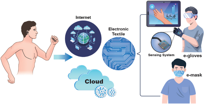
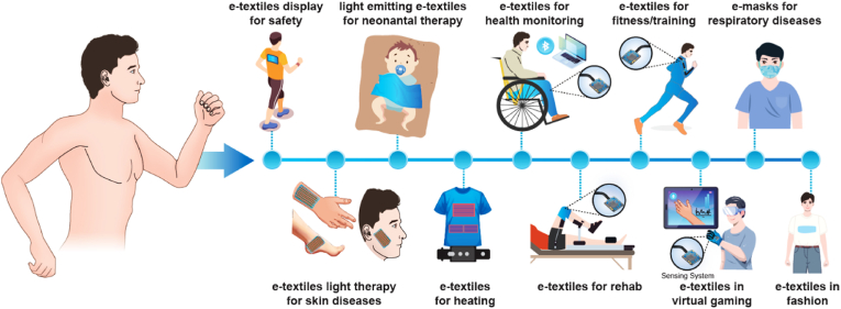
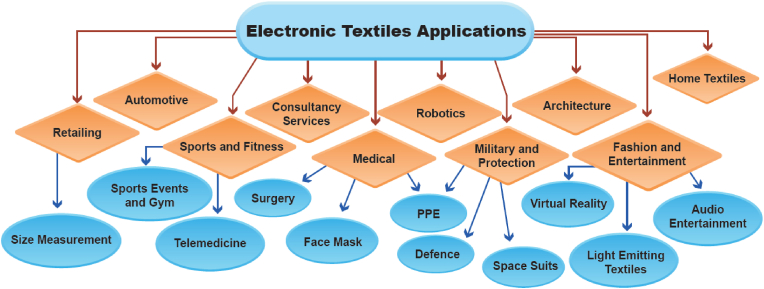
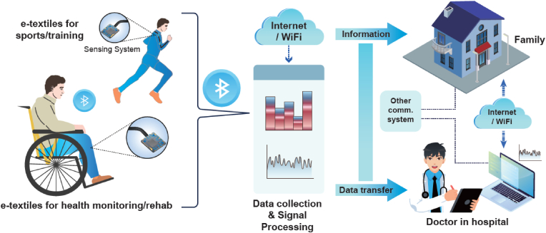
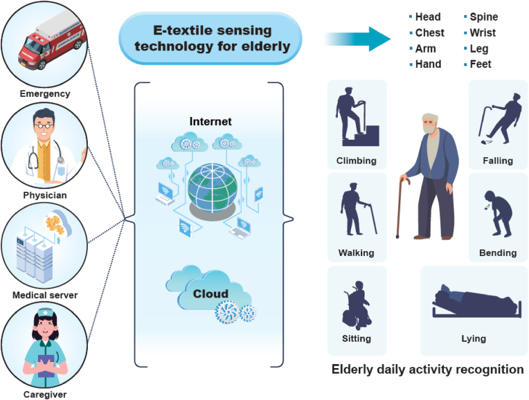
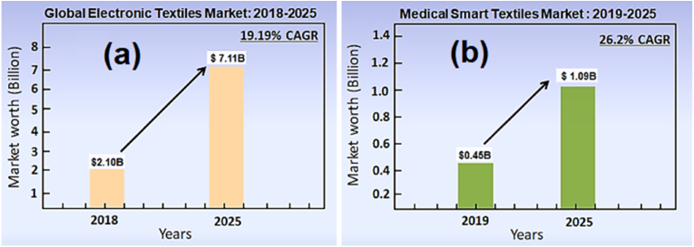
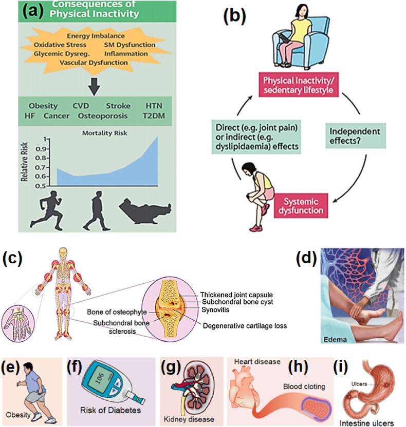
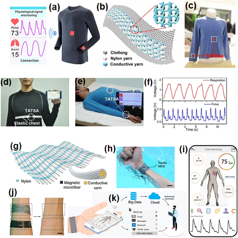
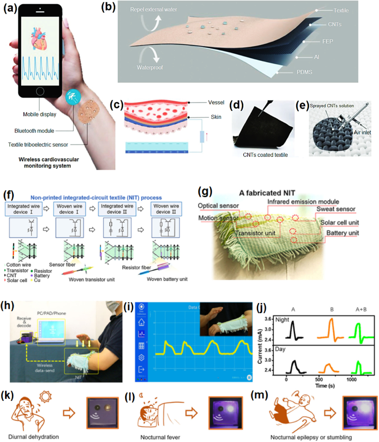
Sedentary lifestyles and evolving work environments have created challenges for global health and cause huge burdens on healthcare and fitness systems. Physical immobility and functional losses due to aging are two main reasons for noncommunicable disease mortality. Smart electronic textiles (e-textiles) have attracted considerable attention because of their potential uses in health monitoring, rehabilitation, and training assessment applications. Interactive textiles integrated with electronic devices and algorithms can be used to gather, process, and digitize data on human body motion in real time for purposes such as electrotherapy, improving blood circulation, and promoting wound healing. This review summarizes research advances on e-textiles designed for wearable healthcare and fitness systems. The significance of e-textiles, key applications, and future demand expectations are addressed in this review. Various health conditions and fitness problems and possible solutions involving the use of multifunctional interactive garments are discussed. A brief discussion of essential materials and basic procedures used to fabricate wearable e-textiles are included. Finally, the current challenges, possible solutions, opportunities, and future perspectives in the area of smart textiles are discussed.

Keywords: Digital health; Light therapy; Smart textiles; Wearable electronics; e-textiles.


Conflict of interest statement

The authors declare that they have no known competing financial interests or personal relationships that could have appeared to influence the work reported in this paper.

Figures

Image 1
Graphical abstract
Fig. 1
Fig. 1
(a) Total research papers and patents yearly publications in past 10 years in area of e-textiles and smart textiles or intelligent garments. (b) Total research articles and patents published in the area of e-textiles, smart textiles and intelligent garments for healthcare and fitness applications. Data Source: Lens Scholarly Search, LENS.ORG.
Fig. 2
Fig. 2
Schematic illustration of a pathway of e-textile applications in different areas.
Fig. 3
Fig. 3
Summarize the development of the e-textiles from phase-one to the current fourth-generation phase. (a) Embroider mark (top); placing of the flexible circuitry device along with the marker, and then embroidered through the contact pads sequentially. Images are reproduced with permission [64], Copyright 2005, IEEE Publishing Group. (b) Interlocked knitted fabric using different stitch patterns (top) resulted in dense fabric (middle) and the concept illustration of a garment integrated with sensing device; insets show actual device prototypes. Images are reproduced with permission [66], Copyright 2019, Wiley-VCH Publishing Group. (c) Illustration of embedding flexible-stretchable electronic strips (top) microscopic image and woven electronic strip in a knit textile (middle) and showing its conformability to the wearer. Images are reproduced with permission [41], Copyright 2020, Springer Nature. (d) Real image of a fully integrated textile system comprising of display, keyboard and power supply (top), photograph of multicolor display textile (middle) and concept design displaying brain waves can be decoded into messages that is displaying on a shirt made from a fully functional display textile. Images are reproduced with permission [71] Copyright 2021, Springer Nature. ∗ Information deduced from published research papers/publicly available information.
Fig. 4
Fig. 4
Application areas of e-textiles.
Fig. 5
Fig. 5
Illustration of a remote fitness and health monitoring system based on wearable sensors. The e-textile could access information from real-time body movements from personalized rehabilitation and other physical training/exercise and transmit that data to a smartphone via wireless communication signals (e.g., Bluetooth) and to a home system and clinic/hospital for analysis.
Fig. 6
Fig. 6
Future application of an e-textile sensing system for the care of the elderly to monitor real-time movements (sitting, lying, climbing, walking, bending, and falling) and process data to track daily activity.
Fig. 7
Fig. 7
(a) Global electronic textile market growth for years 2018–2015 and (b) medical smart textile market growth for years 2019–2025, based on quantitative data [113,114].
Fig. 8
Fig. 8
Summarization of various fabric making strategies: (a) weaving, knitting, braiding, nonwoven and 3D formation. Images are reproduced with permission from Ref. [57], Copyright, 2022 Elsevier Ltd., [18], Copyright, 2022 Springer Nature Ltd. (b) Fabric production stages and hierarchy from fibers to multilayers compound fabric. Images are adopted with permission from Ref. [52], Copyright, 2019 Zhengzhou University.
Fig. 9
Fig. 9
(a) Common conductive materials (conductive polymers, carbon materials, metals, MOF and MXene). Images are reproduced with permission from Ref. [18], Copyright, 2022 Springer Nature Ltd. (b) Fabrication techniques (dyeing, dip-coating, jet printing, embroidery, roll-to-roll coating, screen/stencil printing, spray-coating and spinning) using for the development of electrically functional textiles. Images adapted with permission from Ref. [15], Copyright, The Author(s) 2021.
Fig. 10
Fig. 10
(a) Acute respiratory virus propagation by droplets. Reproduced with permission [194]. Copyright 2020, Society to Improve Diagnosis in Medicine. (b) Mechanisms of deposition of inhaled particles in the lung. Reproduced with permission [195]. Copyright 2020, ATS journals. (c) Possible mechanisms of cardiac and lung injury with COVID-19. Reproduced with permission [196]. Copyright 2020, Elsevier. (d) Model of COVID-19 virus entry into the brain and effectual antiviral drugs. Drugs that can cross the blood–brain barrier could be advantageous in treatment strategies. Reproduced with permission [197]. Copyright 2020, Elsevier.
Fig. 11
Fig. 11
(a) Proposed schematic view of triboelectric self-powered mask with multiple layers. The first three layers (left side) function as a triboelectric filter, and the outer layer function as a conducting mesh. (b) Concept design. (c) Working mechanism of the proposed multilayered self-powered prototype mask. Reproduced with permission [204]. Copyright 2020, Elsevier. (d) Sketch of SARS-CoV recovered from fabric when pre-exposed to the electroceutical fabric for 5 ​min and the stock applied on fabric. (e) Digital photograph of fabricated mask used on a volunteer that can generate a weak electric field to destroy the virus. (f) Photomicrographs of electroceutical fabric and SEM images of Ag and Zn dots. (g) Calculation of viral particles from stock applied to fabric and recovered from fabric, when SARS-CoV contacts the electroceutical fabric. ST cells infected with viruses exposed to the electroceutical fabric for 5 ​min each and loss of cell viability. (h & i) Eradication of respiratory coronavirus (CoV) subjected to contact with the charged mask for 5 ​min, which indicates that the effectiveness of the cartridge improves from 85% to approximately 95%. Reproduced with permission [206], Copyright 2021, Springer Nature.
Fig. 12
Fig. 12
(a) Chemical formula for PEI and schematically designed electrospinning technique for creating nonwoven fabric. (b) Digital image of nonwoven PEI fabric produced on a metal sheet. (c) SEM image of nonwoven PEI fibers. (d) Graphic representation of corona charging technique. (e) Smart electric mask. (f) Digital photograph of the mask. (g) Digital image of exhalation producing electricity that illuminates an LCD, which displays the number “6.” Reproduced with permission [210]. Copyright 2017, Elsevier. (h) Schematic representation of cordless self-powered face mask for breath monitoring. Digital images of the smart face mask (i) front and (j) back sides. (k) Digital photograph of demonstration of wireless real-time breath monitoring procedure for an actual application. (l) Screenshot illustrating the quantified constant and consecutive breathing activity during a sequence of normal breathing, rapid breathing, normal breathing, coughing, normal breathing, breath holding, and normal breathing. Reprinted with permission [212]. Copyright 2021, Wiley-VCH GmbH.
Fig. 13
Fig. 13
(a) Consequences of a sedentary lifestyle: mortality risk vs. relative risks. Reproduced with permission [216]. Copyright 2018, Elsevier. (b) Vicious cycle of physical inactivity and/or sedentary lifestyle and systemic dysfunction leads to systematic dysfunctions. Reproduced with permission [217]. Copyright 2017, Macmillan Publishers, Ltd. (c) Schematic illustration of osteoarthritis, which affects all of the joints in the human body. Reproduced with permission [218]. Copyright 2019, Taylor & Francis Group. (d) Edema: fluid accumulation or swelling. Reproduced with permission [220]. Copyright 2013, American Academy of Family Physicians. Other risks, such as (e) obesity, (f) diabetes, and (g) kidney disease. Reproduced with permission [221]. Copyright 2018, Elsevier. (h) Heart diseases and blood clotting. Reproduced with permission [222]. Copyright 2018, Springer Nature. (i) Intestinal ulcers. Reproduced with permission [223]. Copyright 2017, Elsevier.
Fig. 14
Fig. 14
(a) Sensors stitched into a t-shirt for monitoring of respiratory and pulse signals. (b) Schematic graphic design of sensor and fabric. Inset: an enlarged picture of the sensor. (c) Photograph of fabric sensors seamlessly sewn into a shirt. (d) Photograph of TATSA positioned on the chest for monitoring pressure signals associated with breathing. (e) Photograph of two TATSAs located on the wrist and abdomen for measurement of pulse and respiration, respectively, while a volunteer is sleeping. (f) Signals as heartbeat and respiratory waveforms. Reproduced with permission [161]. Copyright 2020, AAAS Publications. (g) Schematic design of the textile MEG. (h) Photograph of wearable textile-based pulse sensor as a smart wristband to measure cardiovascular parameters under water without encapsulation for telehealth use. (i) User interface on a smartphone application. (j) Digital photograph showing effects of the use of a wearable textile-based MEG and a magnetic wrist strap on skin rashes. (k) Schematic representation of two ways health data can be transmitted either directly to a doctor for instant medical diagnosis or into the cloud for big data analysis. Reproduced with permission [243]. Copyright 2021, Springer Nature.
Fig. 15
Fig. 15
(a) Conceptual design of a self-powered textile triboelectric sensor for heart and blood vessel monitoring that transmits data to a mobile phone. (b) Structure of the triboelectric textile sensor. (c) Working mechanism of the triboelectric textile sensor's generation of electricity in response to a radial artery pulse. (d & e) Digital photographic images showing CNTs textile produced using spray coating technique. Reproduced with permission [255]. Copyright 2021, Wiley-VCH GmbH. NIT textile fabrication methodology scheme: (f) Schematic representation of NIT procedure and an NIT-type IC. (g) Real image of a fabricated wearable and flexible NIT on a textile, similar to a typical IC. (h) Demonstration of detected body motion data transfer from the NIT to a personal computer. (i) Wireless data sketch captured by the NIT sensing system. (j) Captured signals (currents) for different situations (nighttime and daytime) for detection of body movements and sweating. The fabric NIT also functions as an alarm in case of emergencies: (k) as a sound alarm for irregular pH value change, indicating light illumination; (l) as both light and sound alarms for unusual pH value change in the dark; (m) as both sound and light alarms for hitting or stretching on the body in dim light or complete darkness. Reproduced with permission [258]. Copyright 2021, Springer Nature.
Fig. 16
Fig. 16
(a) Configuration of the sensing fabric activated by IL and biocompatible elargol as conductive electrodes. (b) Digital photograph of a cotton fabric decorated with IL. (c & d) Textile sensing unit integrated into shirtsleeve to monitor radial blood vessel pulse signals at wrist. (e) Drawing of human wearing textile sensors and photographs of textile sensors for detecting physiological signals due to human motions. Reproduced with permission [259]. Copyright 2019, Elsevier. (f) Diagram of as-prepared smart e-textile sensor fabricated with two layers, one of Ag as the base electrode and one as a printed bloom-pattern textile as the superstructure, with production process steps and SEM image of Ag-coated textile surface. (g) Digital image of wearable wireless smart textile sensing device for continuous health monitoring with cardiovascular information displayed on a -smartphone screen simultaneously through wireless communication. (h) Textile-based wireless biomonitoring system worn by an elderly woman and the resultant pulse wave signals. Reproduced with permission [262]. Copyright 2019, Elsevier.
Fig. 17
Fig. 17
(a) Schematic diagram of fabrication methodology and structure of PM/PDMS textile. (b) Sketch of PM/PDMS textile on body joints for motion detection. (c) The PM/PDMS textile exhibits excellent performance as a smart strain sensor for several potential applications. (d) Photograph of textile sensor worn on the wrist of a volunteer and illustration of bending textile. The textile sensor captures signals for monitoring (e) elbow bending, (f) fist clenching, (g) walking and running. Reproduced with permission [263]. Copyright 2020, Elsevier. (h) Sketch illustrating (MA)n-type hydrophobic fabric and its use for monitoring human sweating. (i) Optical images of pristine silk and (MA0.3)10F silk. (j) Schematic illustration of MAF silk monitoring of moisture due to sweating. (k) Relative resistance change for MAF silk. The inset shows the moisture response and recovery time. Reproduced with permission [264]. Copyright 2019, Wiley-VCH Verlag GmbH & Co.
Fig. 18
Fig. 18
(a) 24-yr-old female with Fitzpatrick skin acne. Image adapted with permission [268]. Copyright 2014, Authors and Scientific Research Publishing, Inc. (b) A patient with KPR. Image adapted with permission [269]. Copyright 2008, Elsevier. (c) Patients with giant hives (urticaria), Image adapted with permission [2270]. Copyright 2012, Bpac NZ. (d) Eczema on feet of 10-yr-old child. Image adapted with permission [271]. Copyright 2006, MJA Wiley & Sons. (e) Infant with jaundice. (f) Pressing the skin aids in recognition of the yellow color of jaundice. (g) No jaundice sign on the chest while pressing. Image reproduced with permission, update, 2013 [273]. (h) Applications of LED light for the brain, heart tumor, retina, and wound. Image adapted from Ref. [276]. Copyright 2012, Authors and Dove Medical Press, Ltd. (i) Schematic representation of varying depths of light penetration in tissue. Image adapted from Ref. [279] Copyright 2022, MDPI. (j) Skin structure. (k) Usual wound dressing. (l) Wound structure. Reproduced with permission [285]. Copyright 2022, Authors. (For interpretation of the references to color/colour in this figure legend, the reader is referred to the Web version of this article.)
Fig. 19
Fig. 19
(a) An illuminated LEF device coupled with a laser source applies light to both sides of woven optical fibers. (b) Photograph of fabric device before connection with the laser light source. (c) 3-D image of light dispersal across the LEF surface (d) Light-emitting fabrics emitting light of different colors (blue, green, red, and white) with different wavelengths from violet to infrared. (e) Photograph of photodynamic therapy to treat actinic keratosis using a POF-based light-emitting textile at 635 ​nm. Reproduced with permission [293]. Copyright 2020, Authors and LEY-VCH Verlag GmbH & Co. (f) Light intensity and a demonstration of a LED light pixel embedded into clothing from both sides. (g) Photograph of illuminated fabric wrapped around a teddy bear. (h) Photograph of illuminated fabric on baby's body to cure neonatal jaundice by blue light emission. Reproduced with permission [152]. Copyright 2017, Optica Publishing Group. (i) Photograph of photodynamic therapy treatment of actinic keratosis. Reproduced with permission [295]. Copyright 2014, Elsevier.
Fig. 20
Fig. 20
(a) Digital photographs of MXene-fabric (40 ​mm ​× ​10 ​mm) and corresponding IR thermal image at 4 ​V showing the heating characteristic. (b) Illustration of thermotherapeutic use of soft M-fabric integrated into neckpad on a person's neck. (c) Digital image of the use of an M-fabric-integrated neckpad with thermal IR images for different head postures. Reproduced with permission [176], Copyright 2020, American Chemical Society. (d) Illustration of a thread-based patch with a thermoresponsive hydrogel layer painted on a soft and wearable fabric-based electric heater. The inset shows a picture of knitted functional threads as a patch attached to a volunteer's hand. Reproduced with permission [301]. Copyright 2017, Wiley-VCH Verlag GmbH & Co. (e) Schematic illustration of PEDOT-PDA-mSF patch development. (f) Schematic illustration of mSF patch use for diabetic wound therapy. Reproduced with permission [177]. Copyright 2021, Wiley-VCH GmbH.
Fig. 21
Fig. 21
(a) Schematic illustration of printed smart and wearable e-textile sensing clothes and fabrication procedure for custom-made design. (b) Calculated relative resistance changes from signals sensed by smart apparel as a volunteer moved his hands up and down. (c) Real-time monitoring of human movements with smart outfit during states of rest, slow walking, fast walking, and running. Reproduced with permission [178]. Copyright 2022, Wiley-VCH GmbH. (d) Schematic illustration of Ag-coated e-textile strain sensor attached to human body for real-time sensing and data collection on decisive muscle movements. (e–g) Images of fabric sensors on different parts (joints) of the body. Curve of resistance changes in real time during walking and knee movements. Reproduced with permission [163]. Copyright 2017, Wiley-VCH Verlag GmbH. (h) Structure of a pressure sensor matrix plan and its application in sport/training for detecting user postures. (i) Demonstration of gym training performance monitoring using sensor matrix for different exercise situations. Adapted with permission [311] Copyright 2016, Elsevier.
Fig. 21
Fig. 21
(a) Schematic illustration of printed smart and wearable e-textile sensing clothes and fabrication procedure for custom-made design. (b) Calculated relative resistance changes from signals sensed by smart apparel as a volunteer moved his hands up and down. (c) Real-time monitoring of human movements with smart outfit during states of rest, slow walking, fast walking, and running. Reproduced with permission [178]. Copyright 2022, Wiley-VCH GmbH. (d) Schematic illustration of Ag-coated e-textile strain sensor attached to human body for real-time sensing and data collection on decisive muscle movements. (e–g) Images of fabric sensors on different parts (joints) of the body. Curve of resistance changes in real time during walking and knee movements. Reproduced with permission [163]. Copyright 2017, Wiley-VCH Verlag GmbH. (h) Structure of a pressure sensor matrix plan and its application in sport/training for detecting user postures. (i) Demonstration of gym training performance monitoring using sensor matrix for different exercise situations. Adapted with permission [311] Copyright 2016, Elsevier.
Fig. 22
Fig. 22
(a) Near-field-enabled connectivity with a gap of a few cm between the reader and a sensor integrated into a wearable textile. (b) Digital photograph of a smartphone wirelessly supplying power to a sensor node on a relay. Digital images of near-field-enabled (c) shirt and (d) trousers integrated with sensors. Demonstration of workout data measurement with battery-free sensors for comparison of wired (e) and wireless (f) monitoring systems for walking/running that provide strain measurements while connected to a smart mobile phone. (g) Data plotted during the gyroscope phase and strain sensor node. Reproduced with permission [7]. Copyright 2020, Nature Publications. Fabrication steps of knitted sensing wearable. (h) Woven temperature sensor fabricated using graphene-decorated yarns. (i) Wide woven pattern of graphene yarns used in making a temperature sensor. (j) Yarn trail illustration for knitted temperature sensors. (k) Smart t-shirt knitted with textile sensors for sensing the physical state of the human body and transmitting the data to a smartphone application via Bluetooth. Reproduced with permission [164]. Copyright 2019, ACS Publications.
Fig. 23
Fig. 23
Textile-based sensor consisting of four layers (shown in center), (a) breathing rate setup and resistance–time graph, and (b) muscle activity setup and corresponding changes in resistance. Reproduced with permission [315]. Copyright 2020, IEEE. (c) Schematic illustration of fabrication of smart garment with knitted sensing fibers. (d) SEM image of different weaved sensing fibers (glucose, Ag/AgCl) in the textile. (e) Photograph of volunteer wearing a smart textile sensor during running exercise, with data wirelessly transmitted to a smartphone. (f) Results for different sensing fibers knitted into electrochemical sensing fabric as a whole system reference. (g) Comparison of ex-situ data with the in-situ data collected from the sweat samples. Images are reproduced with permission [316]. Copyright 2018, Wiley-VCH Verlag GmbH & Co.
Fig. 24
Fig. 24
(a) Illustration of fabrication of fully-textile pressure sensor. (b) Digital images of the textile sensor, including electrode and spacer fabric dielectric layer. (c) Representation of whole smart motion monitoring textile sensing system for detecting bodily movements and transmitting data wirelessly to a smartphone application. Digital photographs and plotted data for variation in capacitance while the user wore the sensing textile on her elbow and bent the elbow at angles of (d) 30° and (e) 60°. Inset of image (e) shows the schematic circuit design for the motion data detection and transfer. Images reproduced with permission [180], Copyright 2019, American Chemical Society. (f) Schematic illustration of fabricated supercapacitor-integrated strain sensor plus a circuit diagram of the whole system, with digital photographs. (g) Conceptual illustration of the integration of whole sensing system sewn into a nylon glove and a t-shirt for detection of bodily movements. Images reproduced with permission [317], Copyright 2019, American Chemical Society. (h) Schematic design of the fabrication process of the mechanical sensor (strain and pressure) using laser-induced technique for the volleyball game and other sports smart electronic wearable garments. Images are reproduced with permission [318], Copyrights 2022, American Chemical Society.

References

    1. Chen G., Xiao X., Zhao X., Tat T., Bick M., Chen J. Chem. Rev. 2022;122:3259–3291. - PubMed
    1. Wang G., Hou C., Wang H. Wiley-VCH Verlag GmbH & Co.; Germany: 2020. Flexible and Wearable Electronics for Smart Clothing.
    1. Zhang Y., Zhang T., Huang Z., Yang J. Adv. Sci. 2022;9 - PMC - PubMed
    1. Jayathilaka W.A.D.M., Qi K., Qin Y., Chinnappan A., Serrano-García W., Baskar C., Wang H., He J., Cui S., Thomas S.W., Ramakrishna S. Adv. Mater. 2019;31 - PubMed
    1. Zaman S., Tao X., Cochrane C., Koncar V. Electronics. 2022;11:99.

LinkOut - more resources