. 2023 Feb 23;13(1):3159.
doi: 10.1038/s41598-023-29726-2.

Quantification of the methodological error in kinematic evaluation of the DRUJ using dynamic CT

Affiliations

Quantification of the methodological error in kinematic evaluation of the DRUJ using dynamic CT

J G M Oonk et al. Sci Rep. .

Abstract

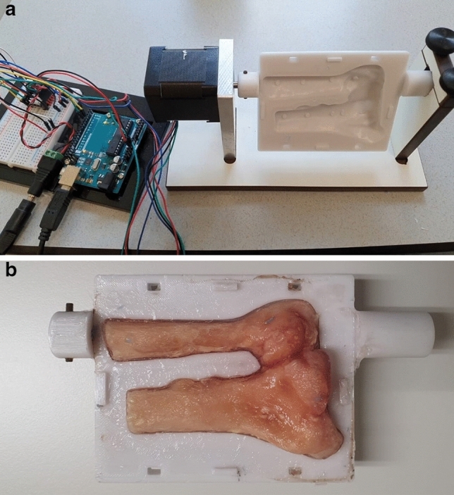
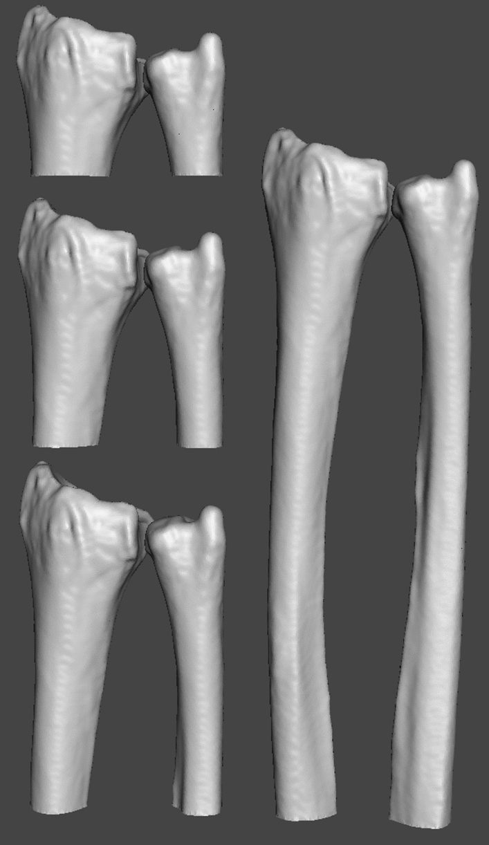
Distal radio-ulnar joint (DRUJ) motion analysis using dynamic CT is gaining popularity. Following scanning and segmentation, 3D bone models are registered to (4D-)CT target frames. Imaging errors like low signal-to-noise ratio (SNR), limited Z-coverage and motion artefacts influence registration, causing misinterpretation of joint motion. This necessitates quantification of the methodological error. A cadaver arm and dynamic phantom were subjected to multiple 4D-CT scans, while varying tube charge-time product and phantom angular velocity, to evaluate the effects of SNR and motion artefacts on registration accuracy and precision. 4D-CT Z-coverage is limited by the scanner. To quantify the effects of different Z-coverages on registration accuracy and precision, 4D-CT was simulated by acquiring multiple spiral 3D-CT scans of the cadaver arm. Z-coverage was varied by clipping the 3D bone models prior to registration. The radius position relative to the ulna was obtained from the segmentation image. Apparent relative displacement seen in the target images is caused by registration errors. Worst-case translations were 0.45, 0.08 and 1.1 mm for SNR-, Z-coverage- and motion-related errors respectively. Worst-case rotations were 0.41, 0.13 and 6.0 degrees. This study showed that quantification of the methodological error enables composition of accurate and precise DRUJ motion scanning protocols.


Conflict of interest statement

The authors declare no competing interests.

Figures

Figure 1
Figure 1
Scanning setup: Cadaveric sample mounted in the hand guiding device.
Figure 2
Figure 2
Motorized phantom: A: The wrist phantom attached to the computer controlled stepper motor with the rotation axis in line with the ulnar shaft. B: Wrist phantom with the DRUJ embedded in agarose gel.
Figure 3
Figure 3
Radius and ulna 3D-model size at different Z-coverages: The 3D-models of the radius and ulna used in registration at four different Z-coverage levels. The cutting plane for the 3D-models was defined using a bounding box on the radius. The height of the bounding box was determined by the desired Z-coverage. The bottom plane of the bounding box was used to clip the 3D-model of the radius as well as the ulna.
Figure 4
Figure 4
SNR induced error: The error in registration at different levels of tube current-time product, leading to different SNR’s. The translational error in mm is shown in the left subgraph, while the rotational error in degrees is given by the right subgraph. All boxplots in this study show the median (horizontal line), interquartile range (IQR) (box), values within the range Q1-1.5*IQR to Q3+1.5*IQR (whiskers) and values outside of the previous range (outliers). Imaging technique: 4D-CT.
Figure 5
Figure 5
Z-coverage induced error: The error in registration at different levels of Z-coverage. The translational error in mm is shown in the left subgraph, while the rotational error in degrees is given in the right subgraph. Imaging technique: serial spiral 3D-CT. *= Z-coverage of scanner used in this study.
Figure 6
Figure 6
Motion artefact induced error: The error in registration when the scanned subject is rotating at different angular velocities. The translational error in mm is shown in the upper subgraph, while the roational error in degrees is given by the lower subgraph. Imaging technique: 4D-CT.
Figure 7
Figure 7
Target frame motion artefacts: CT target images at varying angular velocities. Note the shift from a blurring to a ghosting artefact at speeds greater than ten degrees per second.

References

    1. Shakoor D, et al. Kinematic analysis of the distal radioulnar joint in asymptomatic wrists using 4-dimensional computed tomography-motion pattern and interreader reliability. J. Comput. Assist. Tomogr. 2019;43:392–398. doi: 10.1097/RCT.0000000000000839. - DOI - PubMed
    1. Shores, J. T., Demehri, S. & Chhabra, A. Kinematic, “4 Dimensional” CT Imaging in the Assessment of Wrist Biomechanics Before and After Surgical Repair. Eplasty13, e9 (2013). - PMC - PubMed
    1. Choi YS, et al. Four-dimensional real-time cine images of wrist joint kinematics using dual source CT with minimal time increment scanning. Yonsei Med. J. 2013;54:1026–1032. doi: 10.3349/ymj.2013.54.4.1026. - DOI - PMC - PubMed
    1. Carr R, MacLean S, Slavotinek J, Bain G. Four-dimensional computed tomography scanning for dynamic wrist disorders: Prospective analysis and recommendations for clinical utility. J. Wrist Surg. 2019;08:161–167. doi: 10.1055/s-0038-1675564. - DOI - PMC - PubMed
    1. Verdun, F. R. et al.Image quality in CT: From physical measurements to model observers10.1016/j.ejmp.2015.08.007 (2015). - PubMed