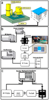
Fabrication and Assembly Techniques for Sub-mm Battery-Free Epicortical Implants
- PMID: 36838175
- PMCID: PMC9966084
- DOI: 10.3390/mi14020476
Fabrication and Assembly Techniques for Sub-mm Battery-Free Epicortical Implants
Abstract
Over the past three decades, we have seen significant advances in the field of wireless implantable medical devices (IMDs) that can interact with the nervous system. To further improve the stability, safety, and distribution of these interfaces, a new class of implantable devices is being developed: single-channel, sub-mm scale, and wireless microelectronic devices. In this research, we describe a new and simple technique for fabricating and assembling a sub-mm, wirelessly powered stimulating implant. The implant consists of an ASIC measuring 900 × 450 × 80 µm3, two PEDOT-coated microelectrodes, an SMD inductor, and a SU-8 coating. The microelectrodes and SMD are directly mounted onto the ASIC. The ultra-small device is powered using electromagnetic (EM) waves in the near-field using a two-coil inductive link and demonstrates a maximum achievable power transfer efficiency (PTE) of 0.17% in the air with a coil separation of 0.5 cm. In vivo experiments conducted on an anesthetized rat verified the efficiency of stimulation.
Keywords: distributed; neural stimulation; wireless power transmission.
Conflict of interest statement
The authors declare no conflict of interest. The funders had no role in the design of the study; in the collection, analyses, or interpretation of data; in the writing of the manuscript; or in the decision to publish the results.
Figures


Similar articles
-
Design and Optimization of a 3-Coil Inductive Link for Efficient Wireless Power Transmission.IEEE Trans Biomed Circuits Syst. 2011 Jul 14;99:1. doi: 10.1109/TBCAS.2011.2158431. IEEE Trans Biomed Circuits Syst. 2011. PMID: 21922034 Free PMC article.
-
A figure-of-merit for design of high performance inductive power transmission links for implantable microelectronic devices.Annu Int Conf IEEE Eng Med Biol Soc. 2012;2012:847-50. doi: 10.1109/EMBC.2012.6346064. Annu Int Conf IEEE Eng Med Biol Soc. 2012. PMID: 23366025 Free PMC article.
-
Fabrication and Microassembly of a mm-Sized Floating Probe for a Distributed Wireless Neural Interface.Micromachines (Basel). 2016 Sep 1;7(9):154. doi: 10.3390/mi7090154. Micromachines (Basel). 2016. PMID: 30404327 Free PMC article.
-
Wireless Power Transfer Strategies for Implantable Bioelectronics.IEEE Rev Biomed Eng. 2017;10:136-161. doi: 10.1109/RBME.2017.2683520. Epub 2017 Mar 16. IEEE Rev Biomed Eng. 2017. PMID: 28328511 Review.
-
Maximizing Data Transmission Rate for Implantable Devices Over a Single Inductive Link: Methodological Review.IEEE Rev Biomed Eng. 2019;12:72-87. doi: 10.1109/RBME.2018.2873817. Epub 2018 Oct 4. IEEE Rev Biomed Eng. 2019. PMID: 30295628 Review.
Cited by
-
Harnessing metamaterials for efficient wireless power transfer for implantable medical devices.Bioelectron Med. 2024 Mar 6;10(1):7. doi: 10.1186/s42234-023-00136-z. Bioelectron Med. 2024. PMID: 38444001 Free PMC article. Review.
-
A method for efficient, rapid, and minimally invasive implantation of individual non-functional motes with penetrating subcellular-diameter carbon fiber electrodes into rat cortex.bioRxiv [Preprint]. 2025 Feb 8:2025.02.05.636655. doi: 10.1101/2025.02.05.636655. bioRxiv. 2025. PMID: 39974888 Free PMC article. Preprint.
References
-
- Lee J., Leung V., Lee A.H., Huang J., Asbeck P., Mercier P.P., Shellhammer S., Larson L., Laiwalla F., Nurmikko A. Neural recording and stimulation using wireless networks of microimplants. Nat. Electron. 2021;4:604–614. doi: 10.1038/s41928-021-00631-8. - DOI
-
- Lee S., Cortese A.J., Mok A., Wu C., Wang T., Park J.U., Smart C., Ghajari S., Khilwani D., Sadeghi S., et al. Fabrication of Injectable Micro-Scale Opto-Electronically Transduced Electrodes (MOTEs) for Physiological Monitoring. J. Microelectromechanical Syst. 2020;29:720–726. doi: 10.1109/JMEMS.2020.2999496. - DOI - PMC - PubMed
-
- Johnson B.C., Shen K., Piech D., Ghanbari M.M., Li K.Y., Neely R., Carmena J.M., Maharbiz M.M., Muller R. timDust: A 6.5mm3, wireless ultrasonic peripheral nerve stimulator with 82% peak chip efficiency; Proceedings of the 2018 IEEE Custom Integrated Circuits Conference (CICC); San Diego, CA, USA. 8–11 April 2018; pp. 1–4. - DOI
Grants and funding
LinkOut - more resources
Full Text Sources
Miscellaneous

