. 2023;7(2):170-181.
doi: 10.1038/s41550-022-01841-6. Epub 2022 Dec 19.

A dehydrated space-weathered skin cloaking the hydrated interior of Ryugu

Takaaki Noguchi  1 Toru Matsumoto  1   2 Akira Miyake  1 Yohei Igami  1 Mitsutaka Haruta  3 Hikaru Saito  4   5 Satoshi Hata  6   7 Yusuke Seto  8 Masaaki Miyahara  9 Naotaka Tomioka  10 Hope A Ishii  11 John P Bradley  11 Kenta K Ohtaki  11 Elena Dobrică  11 Hugues Leroux  12 Corentin Le Guillou  12 Damien Jacob  12 Francisco de la Peña  12 Sylvain Laforet  12 Maya Marinova  13 Falko Langenhorst  14 Dennis Harries  15 Pierre Beck  16 Thi H V Phan  16 Rolando Rebois  16 Neyda M Abreu  17 Jennifer Gray  18 Thomas Zega  19 Pierre-M Zanetta  19 Michelle S Thompson  20 Rhonda Stroud  21 Kate Burgess  22 Brittany A Cymes  23 John C Bridges  24 Leon Hicks  24   25 Martin R Lee  26 Luke Daly  26   27   28 Phil A Bland  29 Michael E Zolensky  30 David R Frank  11 James Martinez  31 Akira Tsuchiyama  32   33   34 Masahiro Yasutake  35 Junya Matsuno  32 Shota Okumura  1 Itaru Mitsukawa  1 Kentaro Uesugi  35 Masayuki Uesugi  35 Akihisa Takeuchi  35 Mingqi Sun  33   34   36 Satomi Enju  37 Aki Takigawa  38 Tatsuhiro Michikami  39 Tomoki Nakamura  40 Megumi Matsumoto  40 Yusuke Nakauchi  41 Masanao Abe  41   42 Masahiko Arakawa  43 Atsushi Fujii  41 Masahiko Hayakawa  41 Naru Hirata  44 Naoyuki Hirata  43 Rie Honda  45 Chikatoshi Honda  44 Satoshi Hosoda  40 Yu-Ichi Iijima  41 Hitoshi Ikeda  41 Masateru Ishiguro  46 Yoshiaki Ishihara  41 Takahiro Iwata  41   42 Kousuke Kawahara  41 Shota Kikuchi  47 Kohei Kitazato  44 Koji Matsumoto  48   42 Moe Matsuoka  41 Yuya Mimasu  41 Akira Miura  41 Tomokatsu Morota  38 Satoru Nakazawa  41 Noriyuki Namiki  48   42 Hirotomo Noda  48   42 Rina Noguchi  49 Naoko Ogawa  41 Kazunori Ogawa  41 Tatsuaki Okada  41   42 Chisato Okamoto  43 Go Ono  41 Masanobu Ozaki  41   42 Takanao Saiki  41 Naoya Sakatani  50 Hirotaka Sawada  41 Hiroki Senshu  47 Yuri Shimaki  41 Kei Shirai  43 Seiji Sugita  38   47 Yuto Takei  41 Hiroshi Takeuchi  41   42 Satoshi Tanaka  41   42 Eri Tatsumi  51   38 Fuyuto Terui  52 Ryudo Tsukizaki  41 Koji Wada  47 Manabu Yamada  47 Tetsuya Yamada  41 Yukio Yamamoto  41 Hajime Yano  41   42 Yasuhiro Yokota  41 Keisuke Yoshihara  41 Makoto Yoshikawa  41   42 Kent Yoshikawa  41 Ryohta Fukai  41 Shizuho Furuya  41 Kentaro Hatakeda  53 Tasuku Hayashi  41 Yuya Hitomi  53 Kazuya Kumagai  53 Akiko Miyazaki  41 Aiko Nakato  41 Masahiro Nishimura  41 Hiromichi Soejima  53 Ayako I Suzuki  53 Tomohiro Usui  41 Toru Yada  41 Daiki Yamamoto  41 Kasumi Yogata  41 Miwa Yoshitake  41 Harold C Connolly Jr  19   54 Dante S Lauretta  19 Hisayoshi Yurimoto  55 Kazuhide Nagashima  11 Noriyuki Kawasaki  55 Naoya Sakamoto  56 Ryuji Okazaki  57 Hikaru Yabuta  9 Hiroshi Naraoka  57 Kanako Sakamoto  41 Shogo Tachibana  58 Sei-Ichiro Watanabe  59 Yuichi Tsuda  41
Affiliations

A dehydrated space-weathered skin cloaking the hydrated interior of Ryugu

Takaaki Noguchi et al. Nat Astron. 2023.

Abstract

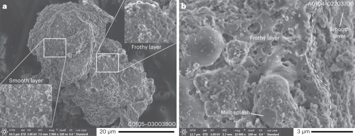
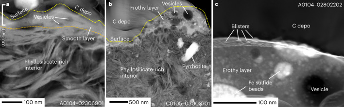
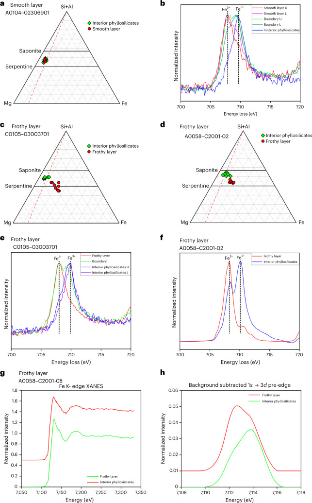
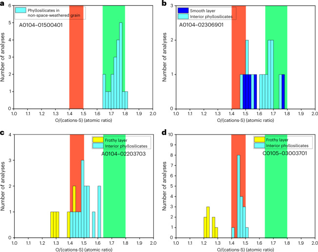
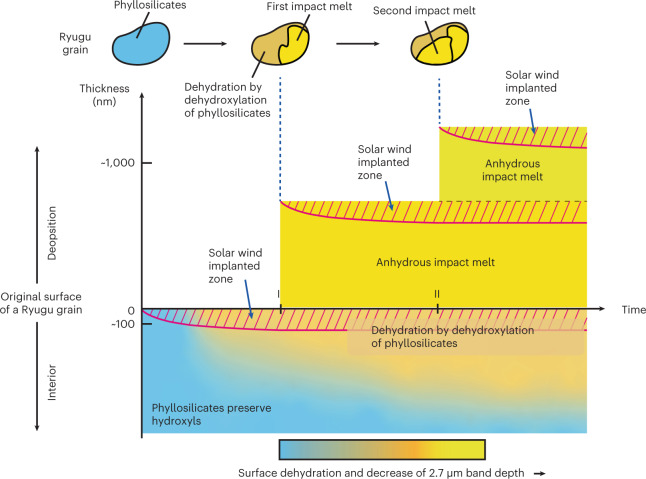
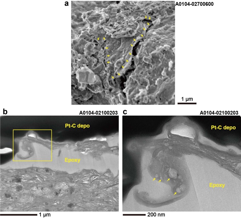
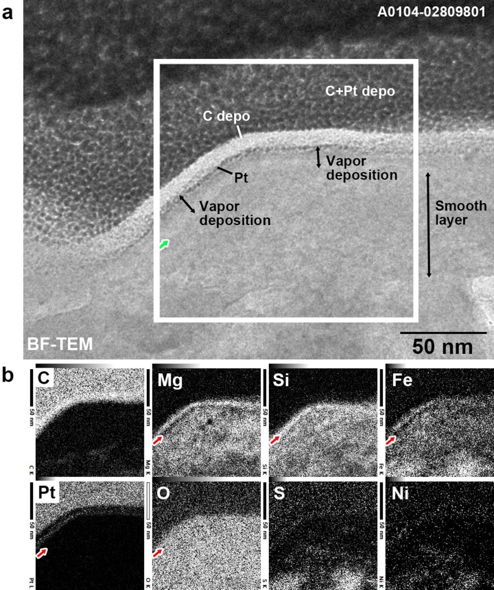
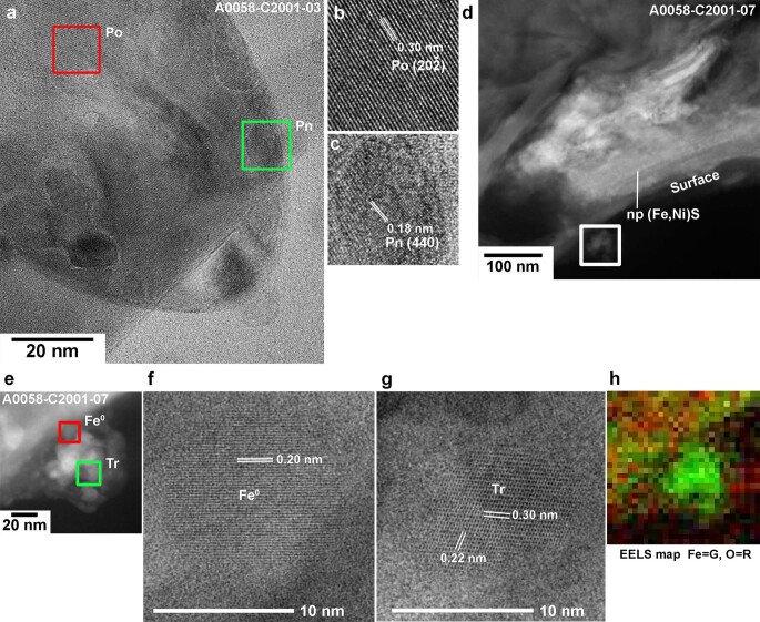
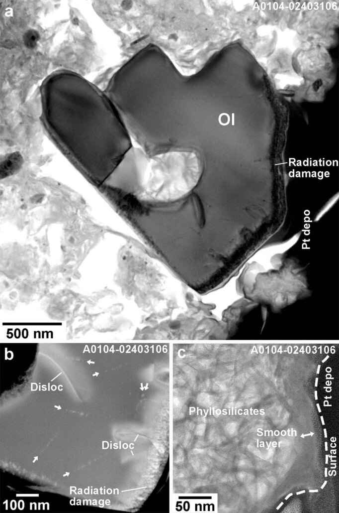
Without a protective atmosphere, space-exposed surfaces of airless Solar System bodies gradually experience an alteration in composition, structure and optical properties through a collective process called space weathering. The return of samples from near-Earth asteroid (162173) Ryugu by Hayabusa2 provides the first opportunity for laboratory study of space-weathering signatures on the most abundant type of inner solar system body: a C-type asteroid, composed of materials largely unchanged since the formation of the Solar System. Weathered Ryugu grains show areas of surface amorphization and partial melting of phyllosilicates, in which reduction from Fe3+ to Fe2+ and dehydration developed. Space weathering probably contributed to dehydration by dehydroxylation of Ryugu surface phyllosilicates that had already lost interlayer water molecules and to weakening of the 2.7 µm hydroxyl (-OH) band in reflectance spectra. For C-type asteroids in general, this indicates that a weak 2.7 µm band can signify space-weathering-induced surface dehydration, rather than bulk volatile loss.

Keywords: Meteoritics; Planetary science.


Conflict of interest statement

Competing interestsThe authors declare no competing interests.

Figures

Fig. 1
Fig. 1. Secondary electron images of Ryugu grains showing surface modifications related to space weathering.
a, The grain C0105–03004800 was collected at the second touchdown site. It is composed of two parts showing different types of space weathering: a frothy layer and a smooth layer. Enlarged images of the two boxed areas on this grain are shown in the insets at the upper right (frothy layer) and the lower left (smooth layer) corners of a. b, The grain A0104–02203700 was collected at the first touchdown site. The frothy layer partially covers the smooth layer on the left-hand side of the image. The boundary between two types of layers is indicated by a dashed curve. The frothy layer has many burst vesicles. A melt splash, located at the lower centre of the image, is attached to the surface of the frothy layer. Source data
Fig. 2
Fig. 2. Cross-sections of three Ryugu grains showing typical surface modifications on the phyllosilicate-rich matrix.
a, The cross-section A0104–02306901 was prepared from the grain A0104–02306900 collected at the first touchdown site. It has a smooth layer that forms a ~100-nm-thick continuous layer covering the surface of the grain. The phyllosilicate-rich matrix is present below the smooth layer. A yellow dashed curve indicates the cross-section of the sample surface. The boundary between the smooth layer and the phyllosilicate-rich interior is indicated by an orange dashed curve. b, The cross-section C0105–03003701 was prepared from the grain C0105–03003700 collected at the second touchdown site. A frothy layer containing abundant vesicles (darker circles) and <50-nm-size brighter spots (Fe-Ni sulfide beads) covers the surface of this grain. The thickness of the frothy layer varies considerably locally from <100 nm to >500 nm. A yellow dashed curve indicates the cross-section of the sample surface. C-depo denotes carbon depositions to protect the surface of the samples during FIB processing. c, An enlarged image of a frothy layer in a cross-section A0104–02802202. The frothy layer contains many tiny (<20 nm across) blisters (vesicles just below the surface) on its surface. These are high-anglular dark-field scanning transmission electron microscope images, in which materials with higher average atomic numbers are brighter than those with lower average atomic numbers. Source data
Fig. 3
Fig. 3. Elemental compositions and redox states of Fe in a smooth layer, frothy layers and the interior phyllosilicates.
a, The ternary [Si+Al]-Mg-Fe atomic-ratio diagram shows that elemental compositions of a smooth layer are indistinguishable from those of the interior phyllosilicates in the cross-section sample A0104–02306901. b, However, a Fe L3-edge peak in EELS spectra shows that Fe2+ is enriched in the smooth layer, which means that Fe3+ in the smooth layer is reduced to Fe2+. The EELS spectra were obtained from the upper (U) and lower (L) parts of the smooth layers, the upper (U) and lower (L) areas around the boundary between the smooth layer and the interior phyllosilicates, and the interior phyllosilicates. c, By contrast, the frothy layer in the cross-section sample C105–03003700 is more enriched in Fe relative to [Si+Al] and Mg than the interior phyllosilicates. d, The same compositional relationship is shown between the frothy layer in the cross-section sample A0058–C2001 and the interior phyllosilicates. The whole grain sizes of these samples are quite different. C105–03003700 and A0058–C2001 are ~30 µm and ~3 mm across, respectively. eh, Fe3+ in the frothy layers is also reduced to Fe2+. e, Fe L3-edge peak spectra obtained by EELS. The spectra were obtained from the frothy layer, the boundary area between the frothy layer and the interior phyllosilicates, and the upper and lower areas of the interior phyllosilicates. f, Fe L3-edge peak spectra obtained by STXM–XANES. g,h, Fe K-edge spectra (g) and background-subtracted pre-edge peak spectra (h) obtained by XANES. Int. phyllosilicates, phyllosilicates in the interior of a sample. Serp and Sap in a, c, and d are the abbreviations for serpentine and saponite, respectively. Source data
Fig. 4
Fig. 4. Histograms of atomic ratios of oxygen to the cations bonded to oxygen in phyllosilicates, a smooth layer and frothy layers.
A mixture of saponite without interlayer H2O molecules and serpentine has a range of ratios represented by green bands. If a mixture of saponite and serpentine is decomposed into an anhydrous compound, it has a range of ratios represented by red bands. In order to calculate the atomic ratios of oxygens to the cations bonded to oxygen in phyllosilicates, we subtracted the cations bonded to sulfur (S), which were calculated based on the assumption that the ratio of the S-bonded Fe and Ni ions to S is unity for simplicity. a, Phyllosilicates in a non-space-weathered grain contain almost no interlayer H2O but preserve structural –OH groups. b, A smooth layer lost a considerable amount of structural –OH groups and phyllosilicates just below the smooth layers partially lost structural –OH groups. c, Phyllosilicates just below the frothy layer have lost the structural –OH groups considerably. d, Phyllosilicates just below the frothy layer have lost almost all the structural –OH groups.Because the frothy layers have even lower ratios than the red bands, they are also anhydrous. Their very low ratios may be related to their high abundance of embedded Fe-Ni sulfide. The ratio at the right end of the green belts is 1.8, which is calculated from the generalized chemical formula of serpentine Y6Z4O10(OH)8. O/(Y + Z) = 18/10 = 1.8. The ratio at the left end of the green belts is 1.64, which is calculated from the generalized chemical formula of saponite with no interlayer H2O molecules X0.6Y6Z8O20(OH)4. O/(X + Y + Z) = 24/14.6 = 1.64. The ratio at the right end of the red belts is 1.5, which is calculated from the generalized chemical formula of the dehydrated decomposition product of saponite X0.6Y6Z8O22. O/(X + Y + Z) = 22/14.6 = 1.5. The ratio at the left end of the red belts is 1.4, which is calculated from the generalized chemical formula of the dehydrated decomposition product of serpentine Y6Z4O14. O/(Y + Z) = 14/10 = 1.4. Source data
Fig. 5
Fig. 5. A conceptual illustration showing the development of two types of space weathering with dehydration by dehydroxylation observed on a Ryugu grain.
Once a surface of a Ryugu grain is exposed to interplanetary space, the effects of solar wind irradiation start to accumulate at and near the surface, which is shown as hatched areas labelled as the ‘Solar wind implanted zone’ in the figure. As time passes, the gradual accumulation of solar wind radiation damage and phyllosilicate dehydroxylation form the smooth layer on its surface with a thickness that seldom exceeds ~100 nm. In contrast, the formation of impact melts (frothy layer, cratering and melt splash) is an intermittent process. In this conceptual illustration, partial coverage by impact melt occurred twice at times I and II. The change of colour from light blue via orange to yellow represents the progress of dehydration. As shown in Fig. 4, the impact melts are almost anhydrous. Therefore, the surface of the model grain is covered by both nearly anhydrous impact melts and dehydroxylated amorphized phyllosilicates. As a result, the surface of the asteroid Ryugu becomes covered by anhydrous material over time. After a long period of space exposure, dehydration by dehydroxylation of the phyllosilicates proceeds below both the smooth layers and the frothy ones. Note that the natural overturn, or gardening, of regolith grains on the asteroid parent body interrupt the schematic history of space weathering so that the space-weathering processes on any one grain do not necessarily progress as shown in Fig. 5.
Extended Data Fig. 1
Extended Data Fig. 1. Histograms of average diameters of fine-grained Ryugu samples investigated in this study.
Grains recovered from both (a) 1st and (b) 2nd touchdown (landing) sites (TD1 and TD2) have a skewed size distribution. No clear differences are observed between size distributions of non-space weathered (blue bins) and space weathered (red bins) grains in both touchdown sites. The proportions of grains with smooth layers, frothy layers, and melt splashes on non-space weathered surfaces are expressed as percentages in both (a) and (b). Bin ranges are 10 µm. Source data
Extended Data Fig. 2
Extended Data Fig. 2. Textural comparison between smooth surfaces and a He+ ion irradiated sample.
Secondary electron (SE) images of (a) a smooth layer on the Ryugu grain A0104–02909600. (b, c) A surface of the non-space weathered Ryugu grain C0107–HE01 (b) before and (c) after a 4 keV He+ irradiation experiment. (d, e) Bright-field (BF) TEM images, diffraction maps, and electron diffraction patterns of (d) natural and (e) artificial smooth layers on Ryugu grains, which are described in (a) and (b), respectively. In both cases, the smooth layers in the cross-section samples A0104–02809802 and C0107–HE01 are amorphized as shown in the insets of electron diffraction patterns #1 in (d) and (e). Source data
Extended Data Fig. 3
Extended Data Fig. 3. Textural Comparison between frothy layers and laser irradiated samples.
(a) SE image of a frothy layer on the Ryugu grain A0104–0223700. (b) Backscattered electron image of the surface of the Murchison CM chondrite after laser irradiation experiment. In both (a) and (b), there are many burst vesicles on grain surfaces. (c) HAADF-STEM image of a frothy layer in a cross-section sample A0058–C2001–02 on the large Ryugu grain A0058–C2001. (d) BF TEM image of the Murchison meteorite cross-section sample after laser irradiation experiment. One of the run products of the laser irradiation experiments performed by Thompson et al. (2019) was used for comparison. Source data
Extended Data Fig. 4
Extended Data Fig. 4. Partially exfoliated smooth layers on phyllosilicate-rich matrix.
(a) Secondary electron image of a smooth layer on the grain A104–02700600. Partial exfoliation of the smooth surface is indicated by yellow arrows. (b-c) BF-TEM image of an exfoliated smooth layer containing vesicles in the cross-section sample A104–02100203. (c)An enlarged image of the area is indicated by a square in (b). The arrows in (c) indicate vesicles in the exfoliated smooth layer. The interstice between the exfoliated layer and the phyllosilicate base is filled by epoxy resin, and Pt-C was deposited by FIB-SEM, both from sample preparation. Source data
Extended Data Fig. 5
Extended Data Fig. 5. 10-nm thick vapor deposit on a smooth layer found in a cross-section sample A104–02809801.
A very thin (~10 nm) layer covers the ~60-nm thick smooth layer. EDS maps show that the upper part of the very thin layer is enriched in Mg, Si, Fe, and O, and the lower part is depleted in Mg, Si, and Fe. There are no detectable differences in concentrations in S and Ni. Because similarly thin top surface layers with such element distribution patterns were reported from Itokawa grains6,7, this top surface layer is considered a vapor deposit on the smooth layer. The estimated boundary between the vapor deposition and the smooth layer is indicated by green or red arrows. This is the only vapor deposit found on the surface of smooth layers investigated. Source data
Extended Data Fig. 6
Extended Data Fig. 6. High-resolution images of sulfide and metal in a frothy layer on the large grain A0058–C2001.
(a) A BF-TEM image of a spherical Fe-Ni sulfide bead in the frothy layer in the cross-section sample A0058-C2001–03. (b, c) Enlarged BF-TEM images of the red and green boxed areas are shown in (b) and (c), respectively. The lattice fringes shown in (b) are 0.30 nm, which suggests 202¯ of pyrrhotite (Po). The fringes shown in (c) are 0.18 nm, suggestive of (4 4 0) of pentlandite (Pn). (d) HAADF-STEM image of the cross-section sample A0058–C2001–07 shows a chain of nanophase (np) (Fe, Ni)S in the thin (~100 nm) smooth layer. (e-h) An aggregate composed of nanophases (<100 nm) on the frothy layer of the cross-section sample A0058–C2001–7. HAADF-STEM image of the aggregate is shown in (e). Enlarged BF-TEM images of the red and green boxed areas in (e) are shown in (f) and (g), respectively. The lattice fringes shown in (b) are 0.30 nm, which suggests 202¯ of pyrrhotite (Po). The fringes shown in (f) is 0.20 nm, suggestive of (1 1 0) of kamacite (Fe°) and those in (g) are 0.22 and 0.30 nm, suggestive of 12¯4, and (1 1 0) of troilite (Tr). (h) EELS map of the same area shown in (e) shows that the aggregate lacks oxygen and contains iron. Source data
Extended Data Fig. 7
Extended Data Fig. 7. An olivine crystal and the surrounding phyllosilicate-rich matrix in the rare olivine-bearing grain A0104–02403200.
(a) BF-TEM image of radiation-damaged olivine and highly porous hydrated matrix in the cross-section sample A0104–02403206, which was prepared from A0104–02403200. (b) Low-angle annular dark-field (LAADF)-STEM image shows that the olivine contains solar flare tracks indicated by arrows as well as dislocations (Disloc) and a radiation damage layer. (c) BF-TEM image shows that a thin (~20 nm) continuous smooth layer covers the phyllosilicate-rich matrix of the cross-section sample A0104–02303204, which was prepared from A0104–02403200. Source data
Extended Data Fig. 8
Extended Data Fig. 8. Exposure age of the surface of a millimeter-sized Ryugu grain A0067 estimated from the impact crater population.
Forty craters with average diameters ranging from 300 nm up to 8.5 µm were examined to estimate the exposure age (see Methods). (a) Secondary electron image of one of the investigated craters. (b) The cumulative impactor flux versus the mass of the impactor, assuming exposure time from 102 years to 105 years (solid lines). Broken lines indicate interplanetary meteoroid flux models at Ryugu’s perihelion (0.96 au [astronomical unit]), average orbit (1.2 au), and aphelion (1.4 au). This diagram shows that the exposure age of the smooth layer-covered surface of A0067 is estimated to be 3 × 104 years, calculated by its crater population and assuming craters formed by interplanetary meteoroid impacts, even if the average semimajor axis of the orbit of Ryugu had changed from 0.96 to 1.4 au. Source data

References

    1. Pieters CM, Noble SK. Space weathering on airless bodies. J. Geophys. Res. Planets. 2016;121:1865–1884. doi: 10.1002/2016JE005128. - DOI - PMC - PubMed
    1. Grier, J. A. & Rivkin, A. S. Airless Bodies of The Inner Solar System (Elsevier, 2019).
    1. Reams, D. V. Solar Energetic Particles 2nd edn (Springer, 2021).
    1. Grün E, Zook HA, Fechtig H, Giese RH. Collisional balance of the meteoritic complex. Icarus. 1985;62:244–272. doi: 10.1016/0019-1035(85)90121-6. - DOI
    1. Nakamura T, et al. Itokawa dust particles: a direct link between S-type asteroids and ordinary chondrites. Science. 2011;333:1113–1116. doi: 10.1126/science.1207758. - DOI - PubMed