

Numerical Design of a Thread-Optimized Gripping System for Lap Joint Testing in a Split Hopkinson Apparatus
- PMID: 36850872
- PMCID: PMC9964832
- DOI: 10.3390/s23042273
Numerical Design of a Thread-Optimized Gripping System for Lap Joint Testing in a Split Hopkinson Apparatus
Abstract
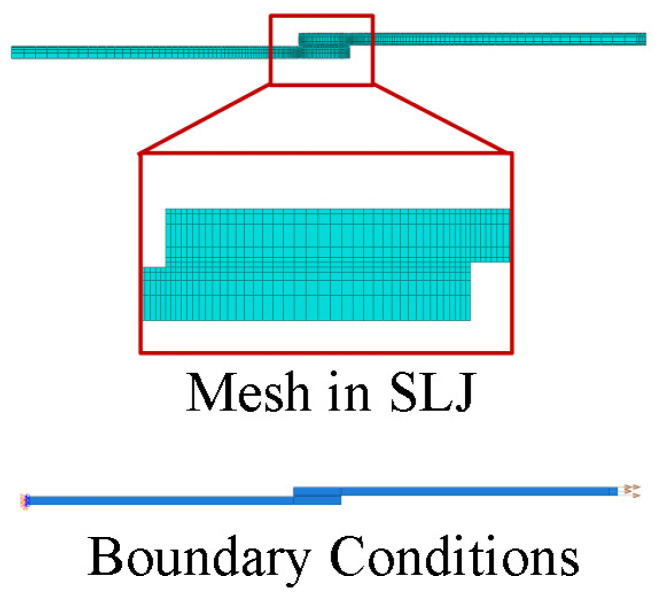
Currently, few experimental methods exist that enable the mechanical characterization of adhesives under high strain rates. One such method is the Split Hopkinson Bar (SHB) test. The mechanical characterization of adhesives is performed using different specimen configurations, such as Single Lap Joint (SLJ) specimens. A gripping system, attached to the bars through threading, was conceived to enable the testing of SLJs. An optimization study for selecting the best thread was performed, analyzing the thread type, the nominal diameter, and the thread pitch. Afterwards, the gripping system geometry was numerically evaluated. The optimal threaded connection for the specimen consists of a trapezoidal thread with a 14 mm diameter and a 2 mm thread pitch. To validate the gripping system, the load-displacement (P-δ) curve of an SLJ, which was simulated as if it were tested on the SHB apparatus, was compared with an analogous curve from a validated drop-weight test numerical model.
Keywords: Single Lap Joint (SLJ); Split Hopkinson Bar (SHB); adhesive; gripping system; high strain rate; impact; thread optimization.
Conflict of interest statement
The authors declare no conflict of interest.
Figures


References
-
- da Silva L.F.M., Öchsner A., Adams R.D. Handbook of Adhesion Technology. 2nd ed. Springer International Publishing AG; New York, NY, USA: 2018.
-
- Machado J.J.M., Marques E.A.S., da Silva L.F.M. Adhesives and adhesive joints under impact loadings: An overview. J. Adhes. 2018;94:421–452. doi: 10.1080/00218464.2017.1282349. - DOI
-
- ASTM International; West Conshohocken, PA, USA: 2003. Standard Test Method for Impact Strength of Adhesive Bonds. - DOI
-
- ISO; Geneva, Switzerland: 1993. Dhesives—Determination of Dynamic Resistance to Cleavage of High-Strength Adhesive Bonds under Impact Wedge Conditions—Wedge Impact Method.
-
- Boland A.J., Lopes A.M., da Silva C.M.S.M., Tenreiro A.F.G., da Silva L.F.M., Nunes D.P., Marques E.A.S., Carbas R.J.C. Development of a Split Hopkinson Pressure Bar Machine for High Strain Rate Testing of Bonded Joints. J. Test. Eval. 2022;50:20200677. doi: 10.1520/JTE20200677. - DOI
Grants and funding
LinkOut - more resources
Full Text Sources
Research Materials
