. 2023 Apr;616(7957):443-447.
doi: 10.1038/s41586-023-05810-5. Epub 2023 Mar 1.

Successful kinetic impact into an asteroid for planetary defence

R Terik Daly #  1 Carolyn M Ernst #  2 Olivier S Barnouin #  2 Nancy L Chabot  2 Andrew S Rivkin  2 Andrew F Cheng  2 Elena Y Adams  2 Harrison F Agrusa  3 Elisabeth D Abel  2 Amy L Alford  2 Erik I Asphaug  4 Justin A Atchison  2 Andrew R Badger  2 Paul Baki  5 Ronald-L Ballouz  2 Dmitriy L Bekker  2 Julie Bellerose  6 Shyam Bhaskaran  6 Bonnie J Buratti  6 Saverio Cambioni  7 Michelle H Chen  2 Steven R Chesley  6 George Chiu  2 Gareth S Collins  8 Matthew W Cox  2 Mallory E DeCoster  2 Peter S Ericksen  2 Raymond C Espiritu  2 Alan S Faber  2 Tony L Farnham  3 Fabio Ferrari  9 Zachary J Fletcher  2 Robert W Gaskell  10 Dawn M Graninger  2 Musad A Haque  2 Patricia A Harrington-Duff  2 Sarah Hefter  2 Isabel Herreros  11 Masatoshi Hirabayashi  12 Philip M Huang  2 Syau-Yun W Hsieh  2 Seth A Jacobson  13 Stephen N Jenkins  2 Mark A Jensenius  2 Jeremy W John  2 Martin Jutzi  14 Tomas Kohout  15   16 Timothy O Krueger  2 Frank E Laipert  6   17 Norberto R Lopez  2 Robert Luther  18 Alice Lucchetti  19 Declan M Mages  6 Simone Marchi  20 Anna C Martin  2 Maria E McQuaide  2 Patrick Michel  21 Nicholas A Moskovitz  22 Ian W Murphy  2 Naomi Murdoch  23 Shantanu P Naidu  6 Hari Nair  2 Michael C Nolan  4 Jens Ormö  11 Maurizio Pajola  19 Eric E Palmer  10 James M Peachey  2 Petr Pravec  24 Sabina D Raducan  14 K T Ramesh  25 Joshua R Ramirez  2 Edward L Reynolds  2 Joshua E Richman  2 Colas Q Robin  23 Luis M Rodriguez  2 Lew M Roufberg  2 Brian P Rush  6 Carolyn A Sawyer  2 Daniel J Scheeres  26 Petr Scheirich  24 Stephen R Schwartz  10 Matthew P Shannon  2 Brett N Shapiro  2 Caitlin E Shearer  2 Evan J Smith  2 R Joshua Steele  2 Jordan K Steckloff  10 Angela M Stickle  2 Jessica M Sunshine  3 Emil A Superfin  2 Zahi B Tarzi  6 Cristina A Thomas  27 Justin R Thomas  2 Josep M Trigo-Rodríguez  28 B Teresa Tropf  2 Andrew T Vaughan  6 Dianna Velez  6 C Dany Waller  2 Daniel S Wilson  2 Kristin A Wortman  2 Yun Zhang  3
Affiliations

Successful kinetic impact into an asteroid for planetary defence

R Terik Daly et al. Nature. 2023 Apr.

Abstract

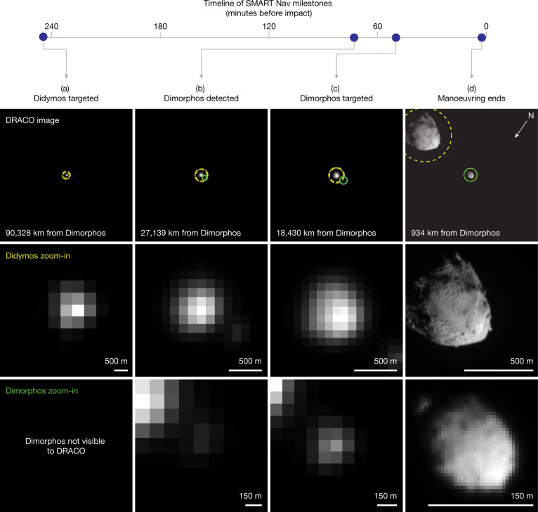
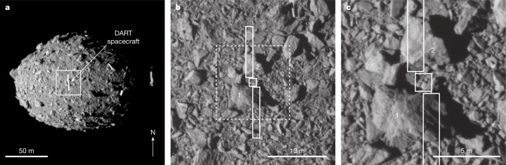
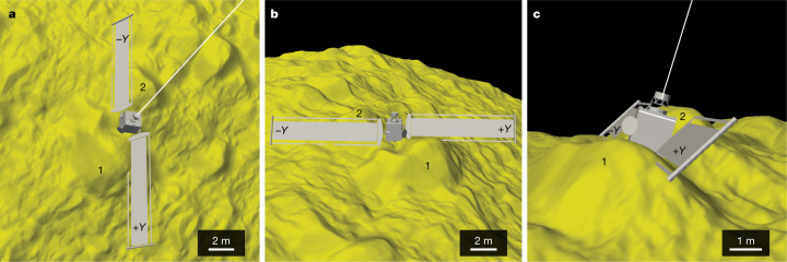
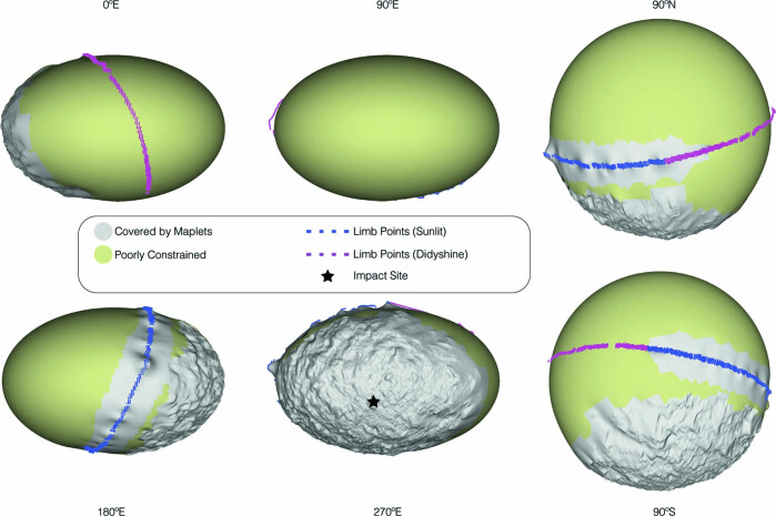
Although no known asteroid poses a threat to Earth for at least the next century, the catalogue of near-Earth asteroids is incomplete for objects whose impacts would produce regional devastation1,2. Several approaches have been proposed to potentially prevent an asteroid impact with Earth by deflecting or disrupting an asteroid1-3. A test of kinetic impact technology was identified as the highest-priority space mission related to asteroid mitigation1. NASA's Double Asteroid Redirection Test (DART) mission is a full-scale test of kinetic impact technology. The mission's target asteroid was Dimorphos, the secondary member of the S-type binary near-Earth asteroid (65803) Didymos. This binary asteroid system was chosen to enable ground-based telescopes to quantify the asteroid deflection caused by the impact of the DART spacecraft4. Although past missions have utilized impactors to investigate the properties of small bodies5,6, those earlier missions were not intended to deflect their targets and did not achieve measurable deflections. Here we report the DART spacecraft's autonomous kinetic impact into Dimorphos and reconstruct the impact event, including the timeline leading to impact, the location and nature of the DART impact site, and the size and shape of Dimorphos. The successful impact of the DART spacecraft with Dimorphos and the resulting change in the orbit of Dimorphos7 demonstrates that kinetic impactor technology is a viable technique to potentially defend Earth if necessary.


Conflict of interest statement

The authors declare no competing interests.

Figures

Fig. 1
Fig. 1. Milestones leading to the impact with Dimorphos from the time SMART Nav began targeting until the end of SMART Nav manoeuvring.
ad, Each column corresponds to a milestone: Didymos targeted (a), Dimorphos detected (b), Dimorphos targeted (c) and end of manoeuvring (d). Each row shows, from top to bottom, the raw DRACO image at the time of that milestone with circles indicating the two asteroids detected by onboard processing and identified by SMART Nav (yellow dashed circles, Didymos; green solid circles, Dimorphos), a zoom-in of Didymos and a zoom-in of Dimorphos. The SMART Nav system used information in DRACO images to successfully impact Dimorphos. In all images, the north pole of Dimorphos (+Z) is towards the bottom left. Images from left to right: dart_0401915351_36903_01_raw.fits, dart_0401925635_06853_01_raw.fits, dart_0401927052_23729_01_raw.fits and dart_0401929899_33346_01_raw.fits.
Fig. 2
Fig. 2. The asteroid Dimorphos and the DART impact site as seen in calibrated DRACO images.
a, Dimorphos with an appropriately scaled and correctly oriented outline of the DART spacecraft centred on the impact site. Note the size of the spacecraft relative to the asteroid. The spacecraft bus was approximately 1.2 × 1.3 × 1.3 m, from which other structures extended, resulting in dimensions of approximately 1.8 × 1.9 × 2.6 m. The spacecraft also had two large solar arrays that were each 8.5 m long. b, A closer view of the DART impact site showing the outline of the spacecraft bus and solar arrays over the DRACO image. Note the positions of the two solar arrays relative to two large boulders, labelled 1 (6.5 m long) and 2 (6.1 m long). This subframe is from an image taken 2.781 s before impact. c, The spacecraft bus hit between boulders 1 and 2, whereas the solar arrays interacted with these boulders. This subframe is from an image taken 1.818 s before impact. The arrow in the bottom right of a indicates the direction of the Dimorphos +Z (north) axis. The solid white box in a shows the location of the image in b. The dashed white box in b shows the location of the image in c. Panels b and c show subimages of the full frame. Image names: dart_0401930039_14119_01_iof.fits (a), dart_0401930048_45552_01_iof.fits (b) and dart_0401930049_43695_01_iof.fits (c).
Fig. 3
Fig. 3. Relationship between the spacecraft and topography at the DART impact site.
ac, The position of the spacecraft immediately before the impact of the spacecraft bus from different perspectives to visualize the three-dimensional interactions between the spacecraft and surface. a, Dimorphos north is towards the top of the panel. b, Dimorphos north is to the right. c, Dimorphos north is roughly into the page. In all panels, the −Y solar array points to Dimorphos north. Length scales vary in these perspective views; the scale bars shown are approximate. Boulders 1 and 2 correspond to boulders 1 and 2 in Fig. 2. The caption to Fig. 2 gives the spacecraft dimensions.
Extended Data Fig. 1
Extended Data Fig. 1. The Dimorphos global digital terrain model (DTM) as viewed along its principal axes.
The black star marks the DART impact site. Colors on the DTM indicate the various constraints used to build the model.
Extended Data Fig. 2
Extended Data Fig. 2. Tilts and topography at the impact site.
DTM of the DART impact site with facets colored by the impact angle with respect to local horizontal, averaged over a 3-m region. The DTM is lit to match the lightning in DRACO images at the time of impact. The white circle shows the uncertainty in the impact location (a circle with a radius of 68 cm). Boulders 1 and 2 correspond to boulders 1 and 2 in Fig. 2. (b) The same DTM with DRACO image dart_0401930048_45552_01_iof.fits draped over it. The image does not cover the entire DTM, so the corners of panel b show the impact angle plate coloring. (c) Histogram of tilts within the white circle representing the uncertainty in the impact site location. (d) – (g) Perspective views of the impact site DTM with overlaid image shown in (b), i.e., the DTM in panel (b) viewed edge on from each of the four sides of the DTM. Boulders 1 and 2 are prominent, as is the small niche between them in which the spacecraft bus hit the surface.
Extended Data Fig. 3
Extended Data Fig. 3. Boulders at the impact site.
(a) Zoomed-in view of the impact site DTM to focus on the two largest boulders near the impact site. Facets in the DTM are colored by the height of the facet along a normal to a plane fit to all of the points in the DTM. DRACO image dart_0401930048_45552_01_iof.fits is draped over the DTM at 40% opacity. The DTM is lit to match the lightning in the DRACO image. The white circle shows the uncertainty in the impact location (a circle with a radius of 68 cm). The red and blue paths show the locations of two topographic profiles across (b) boulder 1 from A to A’ and (c) boulder 2 from B to B’.
Extended Data Fig. 4
Extended Data Fig. 4. Dimorphos and Didymos as seen by DART.
(a) The asteroid Dimorphos seen at a range of pixel scales. Numerous boulders can be distinguished across the surface in images as coarse as 2–3 m pixel scale. Without the context of higher-resolution images, it would be difficult to definitively identify boulders in the 4-m pixel scale image. Image names (from left to right): dart_0401929985_18096_01_iof.fits, dart_0401929952_31226_01_iof.fits, dart_0401929919_44355_01_iof.fits. (b) Composite image of asteroids Dimorphos and Didymos. Dimorphos is at left; Didymos is at right. The two asteroids and the distance between them are to scale. This image was produced by combining two DRACO images to show Dimorphos at higher resolution than Didymos. In spite of the different resolutions, the two surfaces give different first impressions. Dimorphos has a boulder-rich surface with an ellipsoidal shape. Didymos exhibits boulders but also smoother areas and larger concavities. The north poles of Dimorphos and Didymos point to the top of the figure.
Extended Data Fig. 5
Extended Data Fig. 5. The final full DRACO image of Dimorphos’s surface.
Examples of cracks (white arrows), rocks on rocks (squares) and a partially buried boulder are indicated. Image name: dart_0401930049_43695_01_iof.fits. The north pole of Dimorphos is toward the top of the figure.
Extended Data Fig. 6
Extended Data Fig. 6. The size-frequency distribution of boulders identified in the last DRACO full image (dart_0401930049_43695_01_iof.fits).
The limit of image resolution, assuming ≥3 pixel sampling, is ~16.5 cm, so the overturn at small sizes is real and not an observational bias (Pajola et al. 2015). Here, a conservative 5-pixel sampling limit (27.5 cm) is indicated by the vertical blue dashed line. The distribution is not well described by a single power law (shown here as a red dot-dashed line with a slope of −1.65).
Extended Data Fig. 7
Extended Data Fig. 7. Shape modeling process used to build a global digital terrain model of Dimorphos.
The process was informed by shape modeling tests conducted prior to impact.
Extended Data Fig. 8
Extended Data Fig. 8. Sunlit and Didymos-lit limbs of Dimorphos.
The same image of Dimorphos stretched to optimize (a) the limb lit by the Sun and (b) the limb lit by light reflected off Didymos. In (b), pixels with I/F < 0.014 have been scaled up by a factor of 6 to allow the faint features to be seen along with the sunlit features, for better comparison to (a). Together, the two limbs reveal a complete outline of the asteroid as seen by DRACO. The image is dart_0401930039_14119_01_iof.fits.
Extended Data Fig. 9
Extended Data Fig. 9. Shape model assessments.
(a)–(e) show results from limb/terminator shape model assessments. Panels (a)–(c) show an example of (a) a reference DRACO image, (b) the rendered shape model with the same lighting and viewing geometry as the reference image, and (c) the difference between the model and the reference image. (d) and (e) show results from limb/terminator assessments from many DRACO images. (d) Sum of the absolute value of the image-model differences, normalized by the image perimeter. The median is the most relevant measure of uncertainty from this metric because the distribution is always one-sided and never gaussian. (e) The differences in the radii of the equivalent-area circles for the reference image and rendered shape model, respectively. The radius of the equivalent-area circle is the radius of a circle with the same area as the total area of lit terrain on either the rendered model or the reference image. The mean is the most relevant measure of uncertainty from this metric because the distribution should be symmetric. (f)–(i) show results from keypoint assessments. The colored lines in panels (f) and (g) connect features matched by the algorithm in the image and on the shape model. Most, but not all, matches are reasonable, so the median value based on all keypoints is used. (h) shows a metric derived from differences between corresponding keypoints across several tens of DRACO images. (i) shows a model-to-image scale factor derived by comparing the distances measured between all keypoints in the reference DRACO image to the distances measured between all keypoints in images of the rendered shape model. The arrows in panels (a) and (g) indicate the direction of Dimorphos north (+Z).
Extended Data Fig. 10
Extended Data Fig. 10. Fit residuals.
(a) Spacecraft position residuals and (b) residual distributions estimated after fitting the spacecraft locations obtained during the SPC shape modeling process with a second-order polynomial all in the J2000 inertial frame relative to Dimorphos. Uncertainties attributed to the location of the impact site and reported in Table 1 are in the Y and Z axes.

Comment in

References

    1. Defending Planet Earth: Near-Earth Object Surveys and Hazard Mitigation Strategies (National Academies Press, 2010); 10.17226/12842.
    1. Interagency Working Group for Detecting and Mitigating the Impact of Earth-bound Near-Earth Objects National Near-Earth Object Preparedness Strategy and Action Plan (United States National Science & Technology Council, 2018).
    1. Committee on the Planetary Science and Astrobiology Decadal Survey, Space Studies Board, Division on Engineering and Physical Sciences & National Academies of Sciences, Engineering, and Medicine Origins, Worlds, and Life: A Decadal Strategy for Planetary Science and Astrobiology 2023–2032 (National Academies Press, 2022); 10.17226/26522.
    1. Rivkin AS, et al. The Double Asteroid Redirection Test (DART): planetary defense investigations and requirements. Planet. Sci. J. 2021;2:173. doi: 10.3847/PSJ/ac063e. - DOI
    1. A’Hearn MF, et al. Deep impact: excavating comet Tempel 1. Science. 2005;310:258–264. doi: 10.1126/science.1118923. - DOI - PubMed

Publication types