. 2023 Feb 14:11:1116463.
doi: 10.3389/fchem.2023.1116463. eCollection 2023.

A new approach to deposit homogeneous samples of asbestos fibres for toxicological tests in vitro

Affiliations

A new approach to deposit homogeneous samples of asbestos fibres for toxicological tests in vitro

Giancarlo Della Ventura et al. Front Chem. .

Abstract

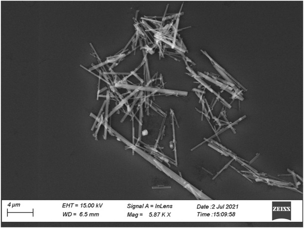
In this paper we describe the results obtained with a novel method to prepare depositions of asbestos fibres for toxicological tests in vitro. The technique is based on a micro-dispenser, working as an inkjet printer, able to deposit micro-sized droplets from a suspension of fibres in a liquid medium; we used here a highly evaporating liquid (ethanol) to reduce the experimental time, however other solvents could be used. Both the amount and spatial distribution of fibres on the substrate can be controlled by adjusting the parameters of the micro-dispenser such as deposition area, deposition time, uniformity and volume of the deposited liquid. Statistical analysis of images obtained by optical and scanning electron microscopy shows that this technique produces an extremely homogeneous distribution of fibers. Specifically, the number of deposited single fibres is maximized (up to 20 times), a feature that is essential when performing viability tests where agglomerated or untangled fibrous particles need to be avoided.

Keywords: asbestos fibres; deposition; image processing; microdrop method; optical and SEM images; toxicological experiments.


Conflict of interest statement

The authors declare that the research was conducted in the absence of any commercial or financial relationships that could be construed as a potential conflict of interest.

Figures

FIGURE 1
FIGURE 1
The deposition process of small particles from an evaporating solution on a hydrophobic surface with a negligible drop-surface interaction (redrawn from Macis et al., 2018).
FIGURE 2
FIGURE 2
Secondary electrons SEM microphotograph of the synthetic amphibole used for the present study.
FIGURE 3
FIGURE 3
The microdrop device (A) and a schematic example of droplets (red spots) deposition pattern (B), where the X-Y distances can be adjusted at any values via the used software (see text for details).
FIGURE 4
FIGURE 4
Optical images of the asbestos depositions obtained with (A) the pipette (drop) and (B) the micro-drop methods, respectively. Optical images taken with ×10 objective lens.
FIGURE 5
FIGURE 5
Optical images from the same sample of Figure 4, at ×40 magnification, showing the distributions of (A) drop and (B) microdrop methods (C, D) corresponding binary images after thresholding and binarization.
FIGURE 6
FIGURE 6
Histograms showing the elongation factor (EF, length/width) of the identified objects for both drop and microdrop deposition methods, respectively. The class of objects with EF > 3 contains fibres according to AIA guidelines. Counts are normalised to mm2.
FIGURE 7
FIGURE 7
Histograms showing the size distribution of the identified objects represented by their area in µm2 (A) and their maximum length in µm (B) for drop and microdrop depositions, respectively. Counts are normalised to mm2.
FIGURE 8
FIGURE 8
The same optical microscopy images as in Figure 5 where asbestiform fibres have been manually annotated as bounding boxes for counting. The choice of the fibres to annotate has been based on NIOSH (Ashley and O'Connor, 2017) counting rules, see text for explanation. (A) Drop and (B) micro-drop depositions.
FIGURE 9
FIGURE 9
Selected SEM images showing asbestiform fibres manually annotated as bounding boxes for counting. The choice of the fibres to annotate has been based on NIOSH (Ashley and O'Connor, 2017) counting rules, see text for explanation. (A) Drop and (B) micro-drop depositions. Note that although the magnification of both images is the same (×800), in the micro-drop deposition the distribution of the particles is extremely more diffused.
FIGURE 10
FIGURE 10
Histograms showing the length size distributions of the manually annotated fibres (see text for explanation) in (A) drop and (B) micro-drop depositions in SEM images. Counts are normalised to 1 mm2.

References

    1. Ashley K., O'Connor P. F. (2017). NIOSH manual of analytical methods (NMAM). 5th edition.
    1. Aust A. E., Cook P. M., Dodson R. F. (2011). Morphological and chemical mechanisms of elongated mineral particle toxicities. J. Toxicol. Env. Health B 14, 40–75. 10.1080/10937404.2011.556046 - DOI - PMC - PubMed
    1. Ballirano P., Bloise A., Gualtieri A. F., Lezzerini M., Pacella A., Perchiazzi N., et al. (2017). The crystal structure of mineral fibres mineral fibres: Crystal-chemistry, chemical-physical properties, biological interactions and toxicity. EMU Notes Mineralogy 18, 17–64. 10.1180/EMU-notes.18.2 - DOI
    1. Belluso E., Cavallo A., Halterman D. (2017). Crystal habit of mineral fibres Mineral fibres: crystal-chemistry, chemical-physical properties, biological interactions and toxicity. EMU Notes Mineralogy 18, 65–110. 10.1180/EMU-notes.18.3 - DOI
    1. Bursi Gandolfi N., Gualtieri A. F., Pollastri S., Ribaldi E., Belpoggi F. (2016). Assessment of asbestos body formation by high resolution FEG–SEM after exposure of Sprague–Dawley rats to chrysotile, crocidolite, or erionite. J. Hazard. Mat. 306, 95–104. 10.1016/j.jhazmat.2015.11.050 - DOI - PubMed

LinkOut - more resources