

Biomechanical investigation of long spinal fusion models using three-dimensional finite element analysis
- PMID: 36890531
- PMCID: PMC9993648
- DOI: 10.1186/s12891-023-06290-4
Biomechanical investigation of long spinal fusion models using three-dimensional finite element analysis
Abstract
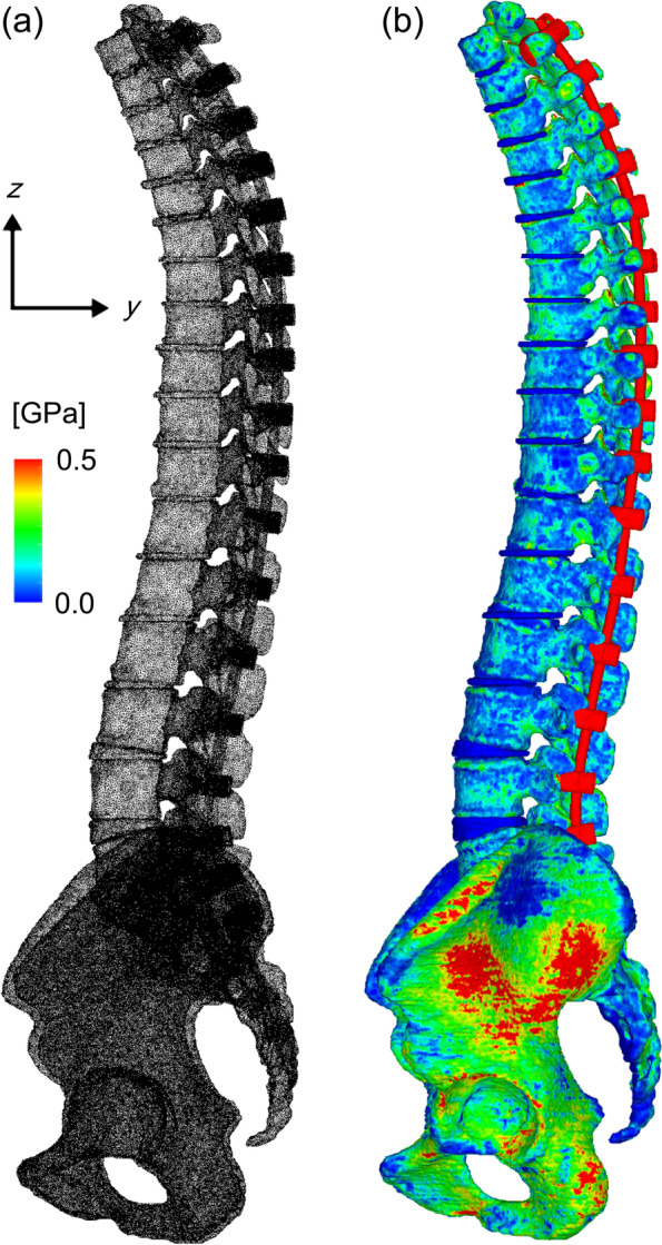
Background: This study represents the first finite element (FE) analysis of long-instrumented spinal fusion from the thoracic vertebrae to the pelvis in the context of adult spinal deformity (ASD) with osteoporosis. We aimed to evaluate the von Mises stress in long spinal instrumentation for models that differ in terms of spinal balance, fusion length, and implant type.
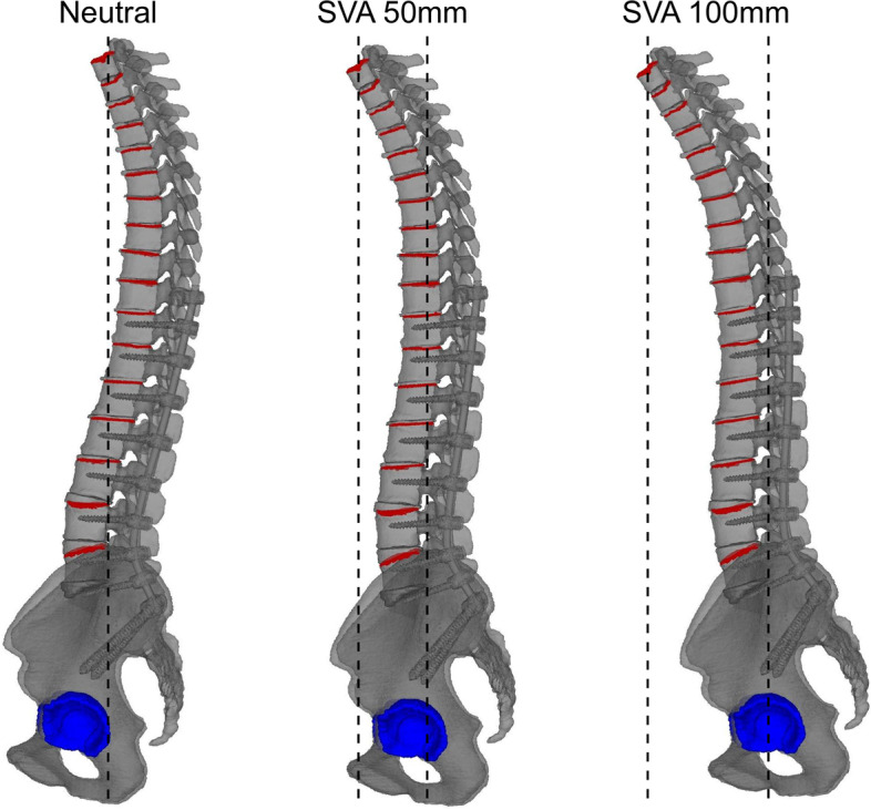
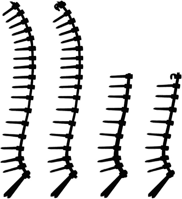
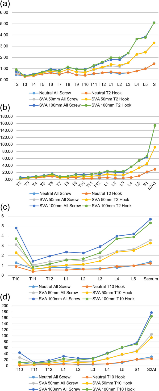
Methods: In this three-dimensional FE analysis, FE models were developed based on computed tomography images from a patient with osteoporosis. The von Mises stress was compared for three different sagittal vertical axes (SVAs) (0, 50, and 100 mm), two different fusion lengths (from the pelvis to the second [T2-S2AI] or 10th thoracic vertebra [T10-S2AI]), and two different types of implants (pedicle screw or transverse hook) in the upper instrumented vertebra (UIV). We created 12 models based on combinations of these conditions.
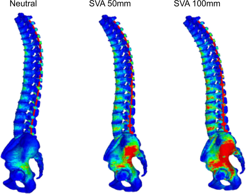
Results: The overall von Mises stress was 3.1 times higher on the vertebrae and 3.9 times higher on implants for the 50-mm SVA models than that for the 0-mm SVA models. Similarly, the values were 5.0 times higher on the vertebrae and 6.9 times higher on implants for the 100-mm SVA models than that for the 0-mm SVA models. Higher SVA was associated with greater stress below the fourth lumbar vertebrae and implants. In the T2-S2AI models, the peaks of vertebral stress were observed at the UIV, at the apex of kyphosis, and below the lower lumbar spine. In the T10-S2AI models, the peaks of stress were observed at the UIV and below the lower lumbar region. The von Mises stress in the UIV was also higher for the screw models than for the hook models.
Conclusion: Higher SVA is associated with greater von Mises stress on the vertebrae and implants. The stress on the UIV is greater for the T10-S2AI models than for the T2-S2AI models. Using transverse hooks instead of screws at the UIV may reduce stress in patients with osteoporosis.
Keywords: Adult spinal deformity; Finite element analysis; Long spinal fusion; Osteoporosis; Pedicle screw; Sagittal vertical axis; Spinal sagittal balance; Transverse hook; Upper instrumented vertebra; Von Mises stress.
© 2023. The Author(s).
Conflict of interest statement
The authors declare that they have no competing interest.
Figures
References
MeSH terms
LinkOut - more resources
Full Text Sources
Medical
Research Materials
Miscellaneous
