. 2022 Mar 8;84(2):170-182.
doi: 10.1055/a-1760-2528. eCollection 2023 Apr.

Anatomical Step-by-Step Dissection of Complex Skull Base Approaches for Trainees: Surgical Anatomy of the Far Lateral Approach

Affiliations

Anatomical Step-by-Step Dissection of Complex Skull Base Approaches for Trainees: Surgical Anatomy of the Far Lateral Approach

Christopher S Graffeo et al. J Neurol Surg B Skull Base. .

Abstract

Introduction Skull base neuroanatomy is classically taught using surgical atlases. Although these texts are critical and rich resources for learning three-dimensional (3D) relationships between key structures, we believe they could be optimized and complemented with step-by-step anatomical dissections to fully meet the learning needs of trainees. Methods Six sides of three formalin-fixed latex-injected specimens were dissected under microscopic magnification. A far lateral craniotomy was performed by each of three neurosurgery resident/fellow at varying stages of training. The study objective was the completion and photodocumentation of the craniotomy to accompany a stepwise description of the exposure to provide a comprehensive, intelligible, and anatomically oriented resource for trainees at any level. Illustrative case examples were prepared to supplement approach dissections. Results The far lateral approach provides a wide and versatile corridor for posterior fossa operation, with access spanning the entire cerebellopontine angle (CPA), foramen magnum, and upper cervical region. Key Steps Include The study includes the following steps: positioning and skin incision, myocutaneous flap, placement of burr holes and sigmoid trough, fashioning of the craniotomy bone flap, bilateral C1 laminectomy, occipital condyle/jugular tubercle drilling, and dural opening. Conclusion Although more cumbersome than the retrosigmoid approach, a far lateral craniotomy offers unparalleled access to lesions centered lower or more medially in the CPA, as well as those with significant extension into the clival or foramen magnum regions. Dissection-based neuroanatomic guides to operative approaches provide a unique and rich resource for trainees to comprehend, prepare for, practice, and perform complex cranial operations, such as the far lateral craniotomy.

Keywords: complex cranial surgery; education; far lateral; foramen magnum; lateral skull base; meningioma; simulation.


Conflict of interest statement

Conflict of Interest None declared.

Figures
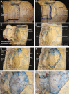
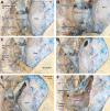
Fig. 1
Fig. 1
( A ) Lateral positioning is preferred for the far lateral craniotomy, with the superior sagittal sinus oriented parallel to the floor. The scalp flap is planned using a hockey stick-style incision, with the major limb in the midline from the C2 spinous process to the superior margin of the transverse sinus, the superior edge paralleling the transverse sinus, and the minor limb descending along the flat part of the mastoid to its tip. ( B ) After the skin is incised and the posterior occipital musculature identified, the epicranial aponeurosis is incised with a 1cm muscle cuff at the superior margin for closure. ( C ) Subperiosteal dissection can then be carried superior to inferior to elevate the single-layer myocutaneous flap, carefully exposing the deep bony and soft tissue structures until the mastoid tip and C2 lamina are reached. ( D ) The flap is covered and padded with cotton sponges, retained in place with fish hook retractors, and bony landmarks are used to approximate the location of the transverse-sigmoid junction, ( E ) where a large burr hole is fashioned, exposing the full margins of the sinus. ( F ) The posterior margin of the descending sigmoid sinus is exposed by drilling a bony trough, a large bone flap is turned extending at least 1cm past the midline and down to the foramen magnum, ( G ) and the dura is carefully stripped off the inner table of the skull as the bone flap is elevated. ( H ) With the bone flap completed, attention is turned to C1, where a wide, bilateral laminectomy is performed. VA, vertebral artery; B., bone.
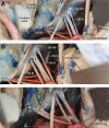
Fig. 2
Fig. 2
( A, B ) Following completion of the C1 laminectomy and wide bony decompression of the foramen magnum, the first dural cut is made in the midline just inferior to the atlanto-occipital membrane. ( C ) The inferior aspect of the dural cut is then extended ipsilateral, maximizing eventual retraction of the dural flap. ( D ) The second dural cut is made at the midpoint of the transverse-sigmoid junction, ( E ) which is then carried inferiorly in a gentle arc toward the superior aspect of the inferior dural cut in the midline. ( F ) The final dural cut communicates the first and second cuts across the atlanto-occipital membrane, which may overlie a patent marginal sinus that should be controlled with vascular clips if needed. VA, vertebral artery; B, bone.
Fig. 3
Fig. 3
( A ) The dural flap is elevated, maximally retracted toward the ipsilateral bony margin, and retained in place with several silk sutures that are sewn to the overlying musculature in a low-profile fashion. The standard far lateral exposure provides wide access to the posterior fossa and upper cervical contents, including the C1–2 region inferiorly, where the C1 rootlets, and spinal contribution of XI are visualized along the posterior cord. ( B ) The V4 segment is encountered intradurally, which typically overlies and may be entangled with the XII rootlets as they exit the brainstem adjacent to the olive, traverse the ventral posterior fossa, and pass through the skull base ventrolaterally at the hypoglossal foramen. Coursing posteriorly along the V4 segment, the distal PICA is encountered which has a highly variable course between patients. ( C ) Gentle infrafloccular retraction and inferior-to-superior angulation brings into view the jugular foramen and IAC, as well as the proximal roots of cranial nerves VII–X, the choroid plexus emerging from the foramen of Luschka overlying IX, and more of the distal PICA. ( D ) Endoscopic views of the jugular foramen show typical nerve configuration, including a single XI root and three–eight rootlets of X occupying the pars venosa inferolaterally, as well as a single IX rootlet passing through the pars nervosa superomedially. ( E ) Deep and medial, VI is noted passing through the clivus at Dorello's canal, ( F ) while superomedially V is visualized entering Meckel's cave, deep to VII-VIII complex and adjacent to Dandy's vein entering the petrous temporal bone to join the superior petrosal sinus. CN, cranial nerve; IAC, internal auditory canal; PICA, posterior cerebellar artery; VA, vertebral artery.
Fig. 4
Fig. 4
( AL ) Side-by-side depictions of sequential drilling of the occipital condyle and adjacent structures, showing the extradural bony resection and resulting intradural access associated with each stepwise extension of the approach. In sequence, these include ( A, B ) fully intact condyle, with part of the occipital squama ( C, D ) drilling up to the condyle, ( E , F ) partial drilling of the condyle, ( G–J ) condylar resection up to the hypoglossal canal with jugular tubercle drilling discretely open the intradural space ( K, L ) Still further access can be gained via the “extreme lateral” variant, which involves unroofing of the foramen transversarium, ( M ) opening of the hypoglossal canal, ( N ) and mobilization of the VA out of the foramen transversarium into a contralaterally reflected position. This maneuver provides access to the anterior arch of C1 and further into the odontoid with continued drilling. The intradural access in the posterior fossa is restricted by the hypoglossal and lower cranial nerves entering their respective foramina AICA, anterior cerebellar artery; CN, cranial nerve; PICA, posterior cerebellar artery; VA, vertebal artery.
Fig. 5
Fig. 5
( A , B ) Detail views of the additional exposure gained by drilling of the jugular tubercle include ready access to the hypoglossal rootlets and ventral contents of the foramen magnum and premedullary cistern. ( C ) Complete jugular tubercle resection, VA transposition, and opening of the hypoglossal canal provide access to lesions within the anterolateral clivus, hypoglossal region, and V4 segment. CN, cranial nerve; VA, vertebal artery.
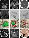
Fig. 6
Fig. 6
( A ) Representative images from case 1 with preoperative MRI sequences including axial DWI and coronal T1, demonstrating a large, left-sided, heterogeneous, prepeduncular, CPA, and foramen magnum lesion with markedly restricted diffusion, most consistent with epidermoid. 3D model fusion of preoperative MRI and postoperative head CT demonstrates the corridor provided by the fat lateral approach for this lesion. Postoperative MRI confirmed gross total resection. ( B ) Representative images from case 2 include T1-weighted, contrast-enhanced, preoperative MRI in the axial plane, as well as a preoperative digital subtraction angiogram (DSA), lateral projection angiogram. The vividly enhancing cerebellar lesion filled robustly with contrast, suggestive of a hemangioblastoma. Preoperative MRI and DSA were fused with postoperative head CT to again demonstrate the far lateral approach to the lesion. Postoperative imaging demonstrated gross total resection. ( C ) Representative images from case 3 include a CT angiogram in the coronal plane and a lateral projection DSA with right external carotid artery injection, demonstrating a tangle of vessels in the posterior foramen magnum with external-to-internal circulatory shunting, indicative of a hypoglossal dural arteriovenous fistula. Pre- and postoperative CTA were fused to demonstrate the surgical corridor to this lesion provided by the far lateral craniotomy. Postoperative imaging confirmed clip ligation of the fistula. 3D, three-dimensional; CPA, cerebellopontine angle; CT, computed tomography; MRI, magnetic resonance imaging.
None

Similar articles

Cited by

References

    1. Rhoton A L., JrThe far-lateral approach and its transcondylar, supracondylar, and paracondylar extensions Neurosurgery 200047(3, suppl)S195–S209. - PubMed
    1. Graffeo C S, Peris-Celda M, Perry A, Carlstrom L P, Driscoll C LW, Link M J. Anatomical step-by-step dissection of complex skull base approaches for trainees: surgical anatomy of the retrosigmoid approach. J Neurol Surg B Skull Base. 2021;82(03):321–332. - PMC - PubMed
    1. Leonel L CPC, Carlstrom L P, Graffeo C S.Foundations of advanced neuroanatomy: technical guidelines for specimen preparation, dissection, and 3D-photodocumentation in a surgical anatomy laboratory J Neurol Surg B Skull Base 202182(suppl 3):e248–e258. - PMC - PubMed
    1. Graffeo C S, Peris-Celda M, Perry A, Carlstrom L P, Driscoll C LW, Link M J. Anatomical step-by-step dissection of complex skull base approaches for trainees: surgical anatomy of the posterior petrosal approach. J Neurol Surg B Skull Base. 2019;80(04):338–351. - PMC - PubMed
    1. Lanzino G, Paolini S, Spetzler R F.Far-lateral approach to the craniocervical junction Neurosurgery 200557(4, suppl) discussion 367–371367–371. - PubMed