. 2023 Feb 22;23(5):2450.
doi: 10.3390/s23052450.

Development of a Real-Time 6-DOF Motion-Tracking System for Robotic Computer-Assisted Implant Surgery

Affiliations

Development of a Real-Time 6-DOF Motion-Tracking System for Robotic Computer-Assisted Implant Surgery

Minki Sin et al. Sensors (Basel). .

Abstract

In this paper, we investigate a motion-tracking system for robotic computer-assisted implant surgery. Failure of the accurate implant positioning may result in significant problems, thus an accurate real-time motion-tracking system is crucial for avoiding these issues in computer-assisted implant surgery. Essential features of the motion-tracking system are analyzed and classified into four categories: workspace, sampling rate, accuracy, and back-drivability. Based on this analysis, requirements for each category have been derived to ensure that the motion-tracking system meets the desired performance criteria. A novel 6-DOF motion-tracking system is proposed which demonstrates high accuracy and back-drivability, making it suitable for use in computer-assisted implant surgery. The results of the experiments confirm the effectiveness of the proposed system in achieving the essential features required for a motion-tracking system in robotic computer-assisted implant surgery.

Keywords: Agile Eye; back-drivability; dental surgery; motion-tracking system; robotic computer-assisted implant surgery.


Conflict of interest statement

The authors declare no conflict of interest.

Figures

Figure 1
Figure 1
Head range of motion: (a) head–neck movement equivalent model; (b) cervical flexion/extension; (c) left/right lateralization; (d) left/right rotation.
Figure 2
Figure 2
The dental splint to connect the motion tracker and the patient.
Figure 3
Figure 3
Simulated target workspace according to target head ROM: (a) schematic diagram of end-effector; (b) perspective view; (c) side view; (d) top view.
Figure 4
Figure 4
Configuration of the translational motion-tracking structure.
Figure 5
Figure 5
The rotational angle-tracking structure based on serial link mechanism.
Figure 6
Figure 6
The rotational angle-tracking structure based on the Agile Eye mechanism: (a) linkage configuration of the one leg of the Agile Eye mechanism; (b) neutral posture; (c) pitch motion of the Agile Eye; (d) yaw motion of the Agile Eye; (e) roll motion of the Agile Eye.
Figure 7
Figure 7
Gravity compensation mechanism for the motion tracker: (a) gravity compensation using spring–balancer mechanism; (b) gravity compensation using counterweight mechanism.
Figure 8
Figure 8
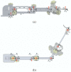
The frame assignments for the proposed link structure: (a) front view; (b) top view.
Figure 9
Figure 9
The frame assignments for the Agile Eye.
Figure 10
Figure 10
The lightweight motion-tracking arm for dental surgery.
Figure 11
Figure 11
Reachable workspace computed via numerical simulation: (a) perpendicular view of the reachable workspace by the translational motion structure; (b) top view of the reachable workspace by the translational motion structure; (c) perpendicular view of the reachable workspace by the entire motion-tracking system; (d) top view of the reachable workspace by the entire motion-tracking system.
Figure 12
Figure 12
Experimental setup to evaluate the positional accuracy. A robot and real-time control platform were used to generate repetitive movement for the developed motion tracking system, and a laser tracker and a Spherical Mounted Retroreflector were used to measure position reference data.
Figure 13
Figure 13
Experimental results on positional accuracy: (a) measured end-effector position from the developed motion-tracking system; (b) sampled points at the origin (red) and the target (blue).
Figure 14
Figure 14
Experimental results on positional accuracy.
Figure 15
Figure 15
Experimental setup to evaluate back-drivability.
Figure 16
Figure 16
Experimental results for back-drivability: (a) trajectories of arbitrary motions generated by the operator; (b) top view of the trajectories; (c) force measured according to arbitrary human motions.

References

    1. Pyo S.W., Lim Y.J., Koo K.T., Lee J. Methods Used to Assess the 3D Accuracy of Dental Implant Positions in Computer-Guided Implant Placement: A Review. J. Clin. Med. 2019;8:54. doi: 10.3390/jcm8010054. - DOI - PMC - PubMed
    1. Tahmaseb A., Wismeijer D., Coucke W., Derksen W. Computer Technology Applications in Surgical Implant Dentistry: A Systematic Review. Int. J. Oral Maxillofac. Implant. 2014;29:25–42. doi: 10.11607/jomi.2014suppl.g1.2. - DOI - PubMed
    1. Kühl S., Zürcher S., Mahid T., Müller-Gerbl M., Filippi A., Cattin P. Accuracy of full guided vs. half-guided implant surgery. Clin. Oral Implant. Res. 2013;24:763–769. - PubMed
    1. Santis D.D., Malchiodi L., Cucchi A., Cybulski A., Verlato G., Gelpi F., Nocini P.F. The Accuracy of Computer-Assisted Implant Surgery Performed Using Fully Guided Templates versus Pilot-Drill Guided Templates. Biomed. Res. Int. 2019;2019:9023548. doi: 10.1155/2019/9023548. - DOI
    1. Park J.M., Kim J., Shim J.S. Review of Computer-assisted Implant Surgeries: Navigation Surgery System vs. Computer-guided Implant Template vs. Robot. Korean Acad. Oral Maxillofac. Implantol. 2018;22:50–58. doi: 10.32542/implantology.20180005. - DOI

LinkOut - more resources