

Numerical approach to investigate MR imaging artifacts from orthopedic implants at different field strengths according to ASTM F2119
- PMID: 36933090
- PMCID: PMC10504103
- DOI: 10.1007/s10334-023-01074-2
Numerical approach to investigate MR imaging artifacts from orthopedic implants at different field strengths according to ASTM F2119
Abstract
Objective: This study presents an extended evaluation of a numerical approach to simulate artifacts of metallic implants in an MR environment.
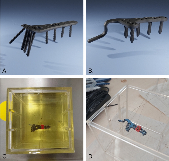
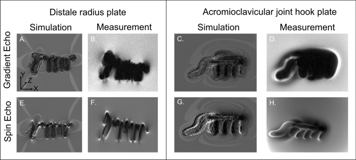
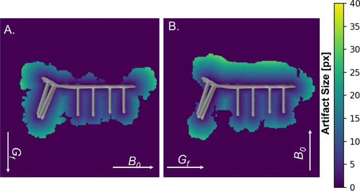
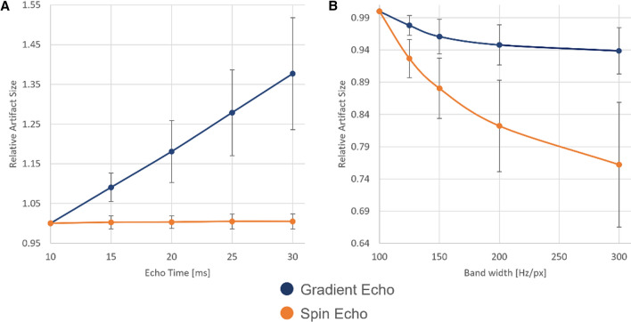
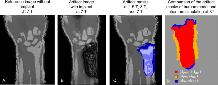
Methods: The numerical approach is validated by comparing the artifact shape of the simulations and measurements of two metallic orthopedic implants at three different field strengths (1.5 T, 3 T, and 7 T). Furthermore, this study presents three additional use cases of the numerical simulation. The first one shows how numerical simulations can improve the artifact size evaluation according to ASTM F2119. The second use case quantifies the influence of different imaging parameters (TE and bandwidth) on the artifact size. Finally, the third use case shows the potential of performing human model artifact simulations.
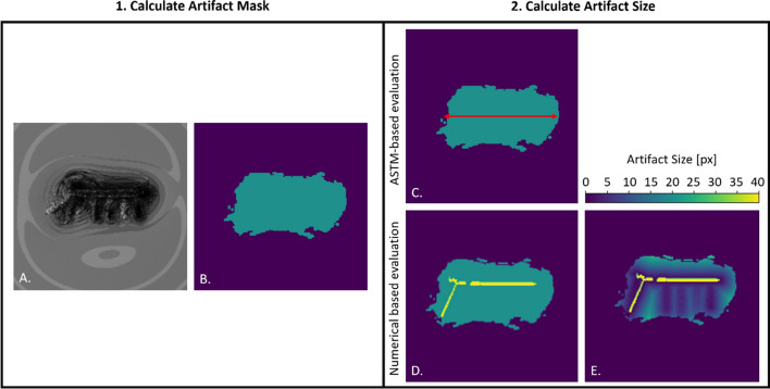
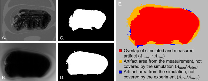
Results: The numerical simulation approach shows a dice similarity coefficient of 0.74 between simulated and measured artifact sizes of metallic implants. The alternative artifact size calculation method presented in this study shows that the artifact size of the ASTM-based method is up to 50% smaller for complex shaped implants compared to the numerical-based approach.
Conclusion: In conclusion, the numerical approach could be used in the future to extend MR safety testing according to a revision of the ASTM F2119 standard and for design optimization during the development process of implants.
Keywords: Artifacts; Human model artifact simulation; Magnetic field strength; Metallic implants; Numeric simulations; Orthopedic implants.
© 2023. The Author(s).
Conflict of interest statement
Tobias Spronk receives salary for MRI-STaR Magnetic Resonance Institute for Safety, Technology and Research GmbH. Oliver Kraff declares that he has no conflicts of interest. Gregor Schaefers is the managing director of MRI-STaR Magnetic Resonance Institute for Safety, Technology and Research GmbH and MR:comp GmbH, Testing Services for MR Safety & Compatibility GmbH. Harald H. Quick declares that he has no conflicts of interest.
Figures
Similar articles
-
Development and evaluation of a numerical simulation approach to predict metal artifacts from passive implants in MRI.MAGMA. 2022 Jun;35(3):485-497. doi: 10.1007/s10334-021-00966-5. Epub 2021 Oct 16. MAGMA. 2022. PMID: 34655346 Free PMC article.
-
[Comparison of susceptibility artifacts generated by microchips with different geometry at 1.5 Tesla magnet resonance imaging. A phantom pilot study referring to the ASTM standard test method F2119-07].Tierarztl Prax Ausg K Kleintiere Heimtiere. 2013;41(5):289-96. Tierarztl Prax Ausg K Kleintiere Heimtiere. 2013. PMID: 24127025 German.
-
Measurement of susceptibility artifacts with histogram-based reference value on magnetic resonance images according to standard ASTM F2119.Biomed Tech (Berl). 2015 Dec;60(6):541-9. doi: 10.1515/bmt-2014-0184. Biomed Tech (Berl). 2015. PMID: 25992509
-
Overcoming artifacts from metallic orthopedic implants at high-field-strength MR imaging and multi-detector CT.Radiographics. 2007 May-Jun;27(3):791-803. doi: 10.1148/rg.273065087. Radiographics. 2007. PMID: 17495293 Review.
-
Metallic Implants in MRI - Hazards and Imaging Artifacts.Rofo. 2021 Nov;193(11):1285-1293. doi: 10.1055/a-1460-8566. Epub 2021 May 12. Rofo. 2021. PMID: 33979870 Review. English.
References
-
- ASTM F2503 (2020) Practice for Marking Medical Devices and Other Items for Safety in the Magnetic Resonance Environment. ASTM International, West Conshohocken, PA. www.astm.org. Accessed 3 Dec 2021
MeSH terms
Grants and funding
LinkOut - more resources
Full Text Sources
