. 2023 Mar 24;14(1):1630.
doi: 10.1038/s41467-023-37294-2.

Direct observation of a superconducting vortex diode

Affiliations

Direct observation of a superconducting vortex diode

Alon Gutfreund et al. Nat Commun. .

Abstract

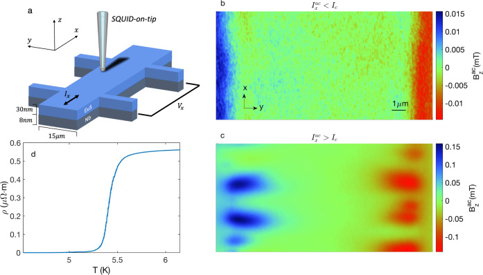
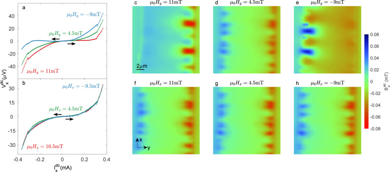
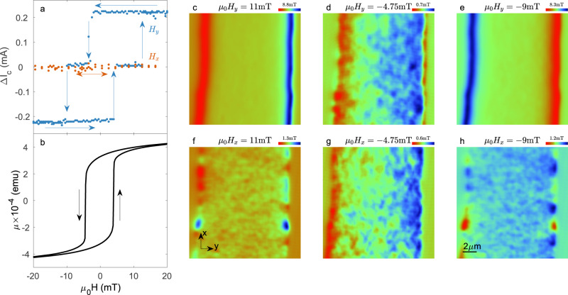
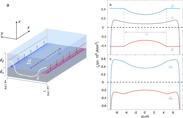
The interplay between magnetism and superconductivity can lead to unconventional proximity and Josephson effects. A related phenomenon that has recently attracted considerable attention is the superconducting diode effect, in which a nonreciprocal critical current emerges. Although superconducting diodes based on superconductor/ferromagnet (S/F) bilayers were demonstrated more than a decade ago, the precise underlying mechanism remains unclear. While not formally linked to this effect, the Fulde-Ferrell-Larkin-Ovchinikov (FFLO) state is a plausible mechanism due to the twofold rotational symmetry breaking caused by the finite center-of-mass-momentum of the Cooper pairs. Here, we directly observe asymmetric vortex dynamics that uncover the mechanism behind the superconducting vortex diode effect in Nb/EuS (S/F) bilayers. Based on our nanoscale SQUID-on-tip (SOT) microscope and supported by in-situ transport measurements, we propose a theoretical model that captures our key results. The key conclusion of our model is that screening currents induced by the stray fields from the F layer are responsible for the measured nonreciprocal critical current. Thus, we determine the origin of the vortex diode effect, which builds a foundation for new device concepts.


Conflict of interest statement

The authors declare no competing interests.

Figures

Fig. 1
Fig. 1. Magnetic response of the EuS/Nb bilayer to an ac current Ixac.
a Schematic diagram of the measurement setup, showing a EuS/Nb Hall bar structure, along with the scanning SQUID-on-tip (SOT) probe. b SOT image of the ac out-of-plane (OOP) component of the magnetic field Bzac(x,y) modulated with respect to an oscillating transport current with root-mean-square (RMS) value Ixac0.15mA < Ic. Blue (red) corresponds to a positive (negative) OOP component of the field emanating from the Nb strip. The device was zero-field cooled to 4.2 K, below the superconducting transition (Tc ~ 5.5 K) and Curie temperature (TC ~ 20 K). c Same as (b) but with RMS value Ixac0.42mA > Ic. In this case, the polarity of the signal depends on whether the magnetic feature appears in phase (blue) or at a π-phase (red) with respect to the oscillating current. The value of the measured magnetic field can be obtained from the color bar on the right side of the images. d R(T) measurements of the device showing the superconducting transition.
Fig. 2
Fig. 2. Vortex flow and corresponding transport measurements as a function of an applied in-plane magnetic field.
a, b I(V) characteristics for different transverse (a) and longitudinal (b) magnetic fields; arrows indicate the direction of the current sweep. The red and blue curves are at fields beyond the saturation field (Hs), while the green curve is at the coercive field. Black arrows indicate that the transport curves were always swept from zero to maximum bias in order to eliminate the effect of hysteresis caused by heating. ch SQUID-on-tip (SOT) image of the ac out-of-plane component of the magnetic field Bzac(x,y) modulated with respect to an oscillating transport current with an RMS value Ixac0.42mA > Ic. The polarity of the signal depends on whether the magnetic feature appears in phase (blue) or at a π-phase (red) with respect to the oscillating current. ce Transverse magnetic field orientation (Hy) with μ0Hy above Hs in the +y direction (c), −y direction (e), and at the coercive field (d). fh Same values of the magnetic field but in a longitudinal orientation, parallel to the direction of current HxIxac. The value of the measured magnetic field can be obtained from the color bar on the right side of the figure. The indicated color scale is the same for all images. For a full set of Bzac(x,y) images, see Supplementary movies 1–2.
Fig. 3
Fig. 3. Correlation between the vortex diode effect and the magnetic texture of EuS.
a Asymmetry factor ΔIc=Ic+Ic as a function of magnetic field for transverse (blue symbols) and longitudinal (red symbols) magnetization. The arrows mark the magnetic field sweep directions. b n-plane M(H) curve of an unpatterned EuS/Nb film with the same thicknesses as our device. ch SQUID-on-tip (SOT) images of the static out-of-plane (OOP) component of the magnetic field Bzdc(x,y) emanating from the EuS/Nb bilayer under various applied in-plane (IP) magnetic fields, as indicated. ce Transverse (Hy) magnetic field orientation with μ0Hy above the saturation field in the +y direction (c), −y direction (e) and at the coercive field (d). fh Same values of magnetic field but in an longitudinal orientation (Hx). The signal range (in mT) for each individual image is noted above the color bar that appears in the top right corner of the image. The center of the scale (green color) is calibrated to the external OOP magnetic field μ0Hz = −5 mT. For a full set of Bzdc(x,y) images, see Supplementary movies 1–2.
Fig. 4
Fig. 4. Theoretical model.
a Schematic diagram of an S (gray)/F (blue) bilayer fully magnetized along the y direction. The orange lines represent auxiliary wires (at y = ±L/2, z = 0) with linear magnetic charge density ± Mdf, which generate a stray magnetic field H. This field induces a screening supercurrent js(y) inside the S film (purple dashed lines) that generates a field in the opposite direction (red and blue arrows). The sum of the fields (B) generated by the S and F layers in the zy plane is represented by the white line. b Calculation of the transport current densities at opposite phases of the ac cycle (blue and red curves) along with the screening current density (purple curve). The central field-free region 2a is depicted by the region between the dashed gray lines. c Total current density jtot (transport + screening) at opposite phases of the ac cycle. In these calculations, the value of It/Ic (which determines the value of a) was set to 0.8, implying that the system is approaching the critical current.

References

    1. Kalcheim Y, Kirzhner T, Koren G, Millo O. Long-range proximity effect in La2/3 Ca1/3MnO3/(100)YBa2Cu3O7−δ ferromagnet/superconductor bilayers: evidence for induced triplet superconductivity in the ferromagnet. Phys. Rev. B. 2011;83:064510. doi: 10.1103/PhysRevB.83.064510. - DOI
    1. Nadj-Perge S, et al. Observation of Majorana fermions in ferromagnetic atomic chains on a superconductor. Science. 2014;346:602. doi: 10.1126/science.1259327. - DOI - PubMed
    1. Linder J, Robinson JWA. Superconducting spintronics. Nat. Phys. 2015;11:307. doi: 10.1038/nphys3242. - DOI
    1. Silaev MA, Bobkova IV, Bobkov AM. Odd triplet superconductivity induced by a moving condensate. Phys. Rev. B. 2020;102:100507. doi: 10.1103/PhysRevB.102.100507. - DOI
    1. Jeon K-R, et al. Exchange-field enhancement of superconducting spin pumping. Phys. Rev. B. 2019;99:024507. doi: 10.1103/PhysRevB.99.024507. - DOI