

Structural Design and Experimental Studies of Resonant Fiber Optic Scanner Driven by Co-Fired Multilayer Piezoelectric Ceramics
- PMID: 36984924
- PMCID: PMC10055889
- DOI: 10.3390/mi14030517
Structural Design and Experimental Studies of Resonant Fiber Optic Scanner Driven by Co-Fired Multilayer Piezoelectric Ceramics
Abstract
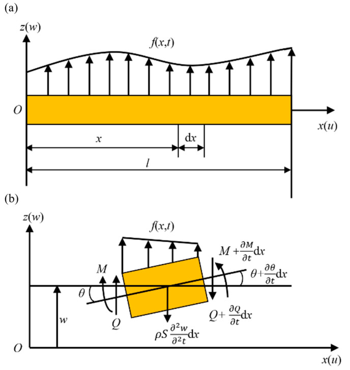
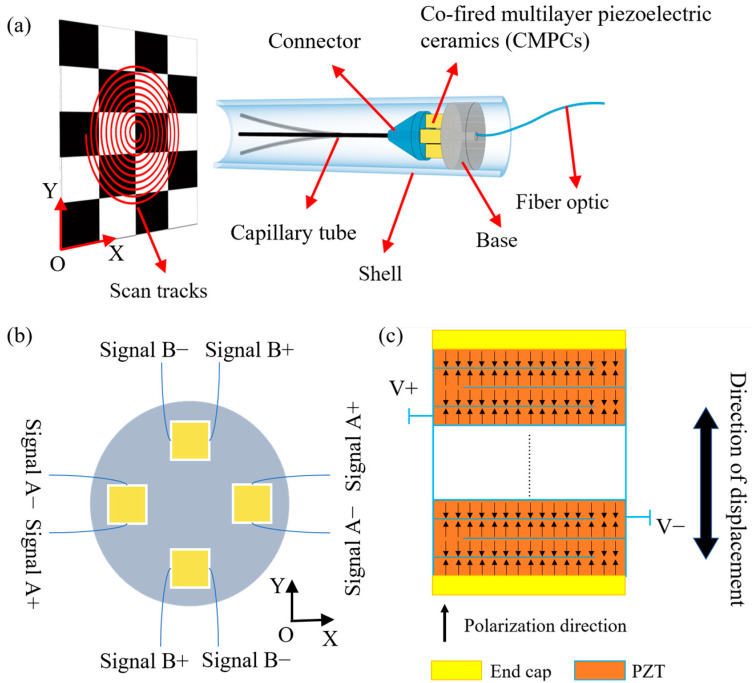
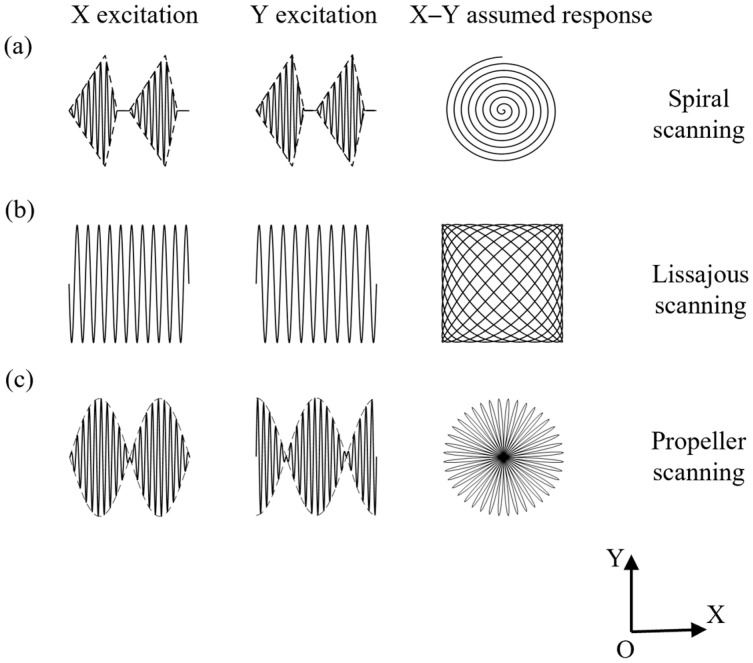
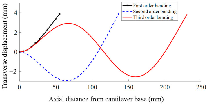
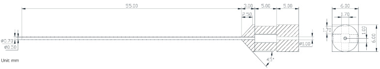
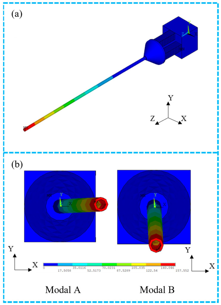
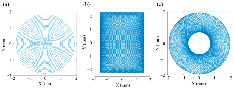
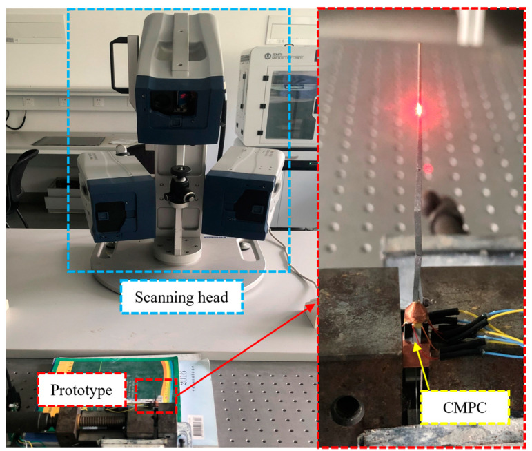
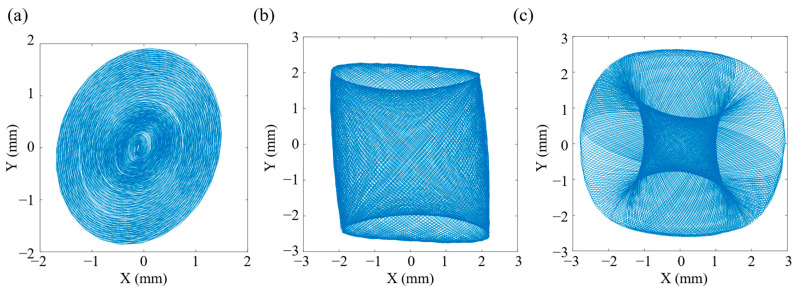
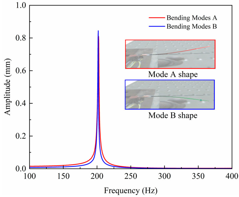
Piezo-driven resonant fiber optic scanners are gaining more and more attention due to their simple structure, weak electromagnetic radiation, and non-friction loss. Conventional piezo-driven resonant fiber optic scanners typically use quadrature piezoelectric tubes (piezo tubes) operating in 31-mode with high drive voltage and low excitation efficiency. In order to solve the abovementioned problem, a resonant fiber scanner driven by co-fired multilayer piezoelectric ceramics (CMPCs) is proposed in which four CMPCs drive a cantilevered fiber optic in the first-order bending mode to achieve efficient and fast space-filling scanning. In this paper, the cantilever beam vibration model with base displacement excitation was derived to provide a theoretical basis for the design of the fiber optic scanner. The finite element method was used to guide the dynamic design of the scanner. Finally, the dynamics characteristics and scanning trajectory of the prepared scanner prototype were tested and compared with the theoretical and simulation calculation results. Experimental results showed that the scanner can achieve three types of space-filling scanning: spiral, Lissajous, and propeller. Compared with the structure using piezo tubes, the designed scanner achieved the same scanning range with smaller axial dimensions, lower drive voltage, and higher efficiency. The scanner can achieve a free end displacement of 10 mm in both horizontal and vertical directions under a sinusoidal excitation signal of 50 Vp-p and 200 Hz. The theoretical, simulation and experimental results validate the feasibility of the proposed scanner structure and provide new ideas for the design of resonant fiber optic scanners.
Keywords: co-fired multilayer piezoelectric ceramics; dynamics characters; fiber optic scanner; finite element method; piezoelectric actuation.
Conflict of interest statement
The authors declare no conflict of interest.
Figures
Similar articles
-
Scanning properties of a resonant fiber-optic piezoelectric scanner.Rev Sci Instrum. 2011 Dec;82(12):123707. doi: 10.1063/1.3671290. Rev Sci Instrum. 2011. PMID: 22225224
-
Note: a resonant fiber-optic piezoelectric scanner achieves a raster pattern by combining two distinct resonances.Rev Sci Instrum. 2012 Aug;83(8):086102. doi: 10.1063/1.4739770. Rev Sci Instrum. 2012. PMID: 22938344
-
Frequency selection rule for the HDHF Lissajous scanning imaging with a low-voltage one axis actuated PZT scanner based on an asymmetric fiber cantilever.Opt Express. 2024 Jan 15;32(2):2774-2785. doi: 10.1364/OE.512263. Opt Express. 2024. PMID: 38297798
-
Potassium Sodium Niobate-Based Lead-Free Piezoelectric Multilayer Ceramics Co-Fired with Nickel Electrodes.Materials (Basel). 2015 Nov 3;8(11):7423-7438. doi: 10.3390/ma8115389. Materials (Basel). 2015. PMID: 28793646 Free PMC article. Review.
-
Scanning and Actuation Techniques for Cantilever-Based Fiber Optic Endoscopic Scanners-A Review.Sensors (Basel). 2021 Jan 2;21(1):251. doi: 10.3390/s21010251. Sensors (Basel). 2021. PMID: 33401728 Free PMC article. Review.
References
-
- Wang X., Seetohul V., Chen R., Zhang Z., Qian M., Shi Z., Yang G., Mu P., Wang C., Huang Z., et al. Development of a Mechanical Scanning Device With High-Frequency Ultrasound Transducer for Ultrasonic Capsule Endoscopy. IEEE Trans. Med. Imaging. 2017;36:1922–1929. doi: 10.1109/TMI.2017.2699973. - DOI - PubMed
-
- Raphael D.T., Li X., Park J., Chen R., Chabok H., Barukh A., Zhou Q., Elgazery M., Kirk Shung K. 20 MHz Forward-Imaging Single-Element Beam Steering with an Internal Rotating Variable-Angle Reflecting Surface: Wire Phantom and Ex Vivo Pilot Study. Ultrasonics. 2013;53:561–569. doi: 10.1016/j.ultras.2012.09.013. - DOI - PMC - PubMed
-
- Dong Z., Li S., Lowerison M.R., Pan J., Zou J., Song P. Fast Acoustic Steering Via Tilting Electromechanical Reflectors (FASTER): A Novel Method for High Volume Rate 3-D Ultrasound Imaging. IEEE Trans. Ultrason. Ferroelectr. Freq. Control. 2021;68:675–687. doi: 10.1109/TUFFC.2020.3020871. - DOI - PMC - PubMed
Grants and funding
LinkOut - more resources
Full Text Sources
