. 2023 Mar 22;14(3):699.
doi: 10.3390/mi14030699.

Fabrication of Chemofluidic Integrated Circuits by Multi-Material Printing

Affiliations

Fabrication of Chemofluidic Integrated Circuits by Multi-Material Printing

Alexander Kutscher et al. Micromachines (Basel). .

Abstract

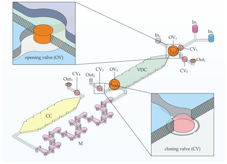
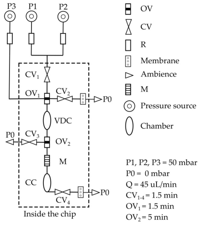
Photolithographic patterning of components and integrated circuits based on active polymers for microfluidics is challenging and not always efficient on a laboratory scale using the traditional mask-based fabrication procedures. Here, we present an alternative manufacturing process based on multi-material 3D printing that can be used to print various active polymers in microfluidic structures that act as microvalves on large-area substrates efficiently in terms of processing time and consumption of active materials with a single machine. Based on the examples of two chemofluidic valve types, hydrogel-based closing valves and PEG-based opening valves, the respective printing procedures, essential influencing variables and special features are discussed, and the components are characterized with regard to their properties and tolerances. The functionality of the concept is demonstrated by a specific chemofluidic chip which automates an analysis procedure typical of clinical chemistry and laboratory medicine. Multi-material 3D printing allows active-material devices to be produced on chip substrates with tolerances comparable to photolithography but is faster and very flexible for small quantities of up to about 50 chips.

Keywords: PEG; chemofluidics; closing and opening valve; hydrogel; microfluidics; printing.


Conflict of interest statement

The authors declare no conflict of interest. The funders had no role in the design of the study; in the collection, analyses, or interpretation of data; in the writing of the manuscript; or in the decision to publish the results.

Figures

Figure 1
Figure 1
Printer setup under protective nitrogen atmosphere inside the glovebox; (a) process of inkjet printing of hydrogel prepolymer solution; (b) UV exposure of the prepolymer solution, (c) pneumatic extrusion of melted PEG for opening-valves and (d) an overview of all tools. The supporting video material (Videos S1 and S2) gives further insight.
Figure 2
Figure 2
General process flow of fabrication of multilayer chemofluidic ICs with multi-material printing. The different valve types are manufactured in separate layers (upper process flow (bd) for hydrogel-based closing valves; lower process flow (eg) for soluble PEG opening valves; (a) laser structuring of the polymer layers, including engraving; (b) ink-jet printing of prepolymer solution; (c) UV exposure of prepolymer solution; (d) alignment, stacking and bonding of the closing valve sub-stack; (e) dispensing of molten PEG; (f) removal of excessive PEG; (g) alignment, stacking and bonding of the opening valve sub-stack; and (h) combination of the sub-stacks to the complete chip with L1 + L3 PMMA foil, L2 + L4 PE foil with adhesive 9960 on both sides, L5 PMMA foil with 9795R on top side.
Figure 3
Figure 3
(a) Schematic cross-section of closing valve layer stack; pink—hydrogel element, blue—fluidic layer; the width of the hydrogel, dHG; the diameter of the valve seat, dVS; the diameter of the engraving, dE; thickness of the foil of fluidic layer, hVS. (b) Top view of dry hydrogel positioned in 475 µm diameter (dVS) valve seat and 600 µm diameter (dE) engraving.
Figure 4
Figure 4
(a) Schematic cross-section of opening valve layer stack; orange—PEG element, blue and violet—fluidic layers.; thickness of the foil with the hole, hVS, and diameter of the hole, dOV. (b) Top view of cured PEG element positioned in 500 µm hole (dOV) and placed between microfluidic layers.
Figure 5
Figure 5
An isometric projection demonstrating the building elements and their arrangement in the application chip for volume definition, incubation and mixing of two liquids. The chip was constructed of six polymeric layers. Two insets showing isometric cross-section cutaways of closing and opening valve. M—3D micromixer, CV—closing valve, OV—opening valve, In—inlet, Out—outlet, VDC—volume definition chamber, CC—collecting chamber. The brown discs at Out1 and Out3 represent the integrated PTFE membranes.
Figure 6
Figure 6
Circuit schematic of the application chip showing the building elements and their arrangements. M—3D micromixer, CV—closing valve, OV—opening valve, VDC—volume definition chamber, CC—collecting chamber, P—pressure, R—resister, Q—flow rate. The opening and closing times of all valves are also indicated. The resister (R) was a 60 cm tubing of a diameter of 0.25 µm provided so high resistance that the resistance caused by the microfluidic building elements was negligible and the flow rate in the chip remained constant.
Figure 7
Figure 7
(a) Side view during printing process, the upper part depicts the tip of the piezoelectric pipette and underneath it the deposited hydrogel prepolymer solution (400 droplets with a volume around 450 pl per drop) inside the circular engraving on a PMMA substrate. (b) Top view of a printed hydrogel (60 s UV exposure time, 400 droplets, ca. 450 pl per drop) after drying, positioned in 600 µm diameter (dE) engraving. (c) Side views of a dry hydrogel (top) and of a swollen hydrogel (bottom), with the same synthesis parameters as in (b).
Figure 8
Figure 8
Dependence of hydrogel valve closing time on valve seat diameter (dVS) (60 s UV exposure time, 400 droplets, ca. 450 pl per drop).
Figure 9
Figure 9
Dependence of the radius of hydrogels in dry state on the UV light exposure time (400 droplets, ca. 450 pl per drop).
Figure 10
Figure 10
Free swelling of hydrogels (60 s UV exposure time, 400 droplets, ca. 450 pl per drop). The average hydrogel area results from three swelling kinetic measurements.
Figure 11
Figure 11
(a) Side view during pneumatic cartridge dispensing printing process, the upper part is the tip of the metallic nozzle of the pneumatic extruder and below is a 500 µm hole in a PMMA foil. (b) Top view of PEG printed and solidified in a hole. (c) Dependence of opening time on diameter of holes (dOV) and thickness (hVS) of PMMA foil.
Figure 12
Figure 12
The chemofluidic application chip executes the circuit program. (a) An unfilled chip ready for operation showing the order of building elements. (b) Liquid 1 (red ink-stained water) and liquid 2 (blue ink-stained water) are simultaneously pumped into VDC at a constant pressure of 50 mbar and a flow rate of 40–45 µL/min. (c) Transportation of the two liquids by liquid 3 (unstained water) through M into CC (d).

References

    1. Hamilton S. Taking Moore’s Law into the next Century. Computer. 1999;32:43–48. doi: 10.1109/2.738303. - DOI
    1. Thorsen T., Maerkl S.J., Quake S.R. Microfluidic Large-Scale Integration. Science (1979) 2002;298:580–584. doi: 10.1126/science.1076996. - DOI - PubMed
    1. Melin J., Quake S.R. Microfluidic Large-Scale Integration: The Evolution of Design Rules for Biological Automation. Annu. Rev. Biophys. Biomol. Struct. 2007;36:213–231. doi: 10.1146/annurev.biophys.36.040306.132646. - DOI - PubMed
    1. Au A.K., Lai H., Utela B.R., Folch A. Microvalves and Micropumps for BioMEMS. Micromachines. 2011;2:179–220. doi: 10.3390/mi2020179. - DOI
    1. Rhee M., Burns M.A. Microfluidic Pneumatic Logic Circuits and Digital Pneumatic Microprocessors for Integrated Microfluidic Systems. Lab Chip. 2009;9:3131–3143. doi: 10.1039/b904354c. - DOI - PMC - PubMed

LinkOut - more resources