. 2023 Mar 30;14(1):1757.
doi: 10.1038/s41467-023-37255-9.

Self assembling nanoparticle enzyme clusters provide access to substrate channeling in multienzymatic cascades

Affiliations

Self assembling nanoparticle enzyme clusters provide access to substrate channeling in multienzymatic cascades

Joyce C Breger et al. Nat Commun. .

Abstract

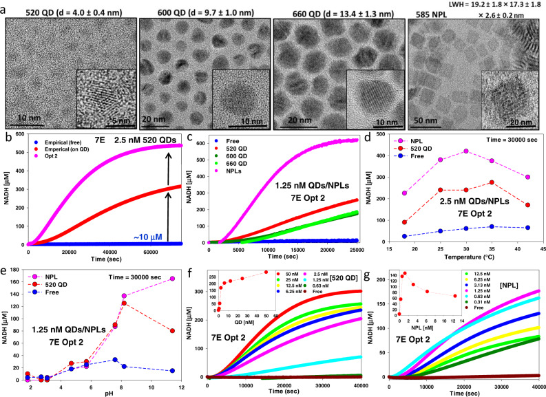
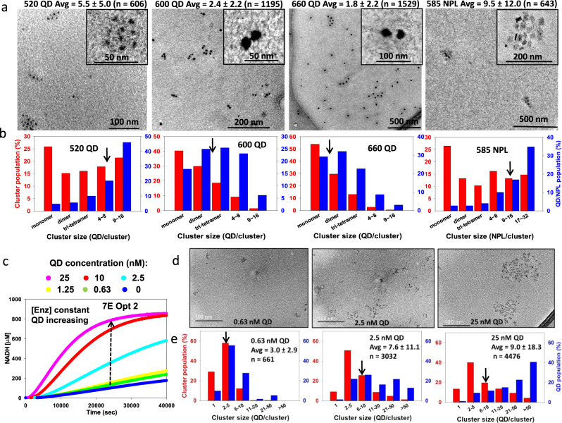
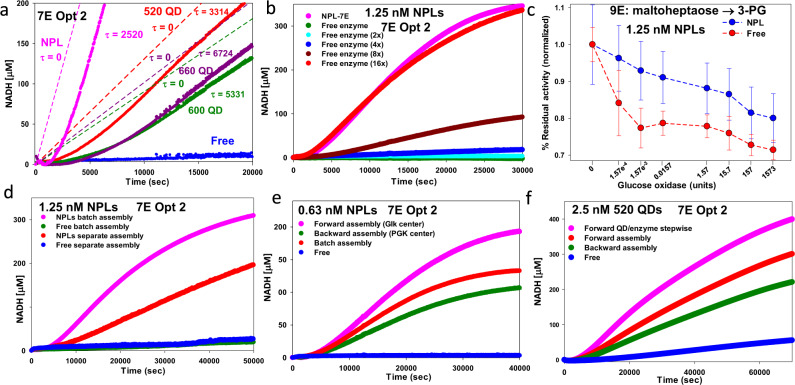
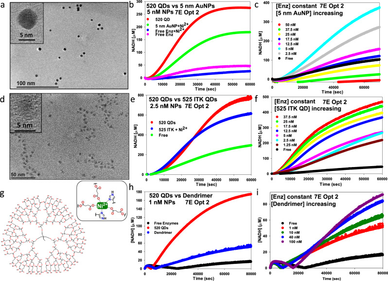
Access to efficient enzymatic channeling is desired for improving all manner of designer biocatalysis. We demonstrate that enzymes constituting a multistep cascade can self-assemble with nanoparticle scaffolds into nanoclusters that access substrate channeling and improve catalytic flux by orders of magnitude. Utilizing saccharification and glycolytic enzymes with quantum dots (QDs) as a model system, nanoclustered-cascades incorporating from 4 to 10 enzymatic steps are prototyped. Along with confirming channeling using classical experiments, its efficiency is enhanced several fold more by optimizing enzymatic stoichiometry with numerical simulations, switching from spherical QDs to 2-D planar nanoplatelets, and by ordering the enzyme assembly. Detailed analyses characterize assembly formation and clarify structure-function properties. For extended cascades with unfavorable kinetics, channeled activity is maintained by splitting at a critical step, purifying end-product from the upstream sub-cascade, and feeding it as a concentrated substrate to the downstream sub-cascade. Generalized applicability is verified by extending to assemblies incorporating other hard and soft nanoparticles. Such self-assembled biocatalytic nanoclusters offer many benefits towards enabling minimalist cell-free synthetic biology.


Conflict of interest statement

I.L.M., J.N.V., M.G.A., K.S., and S.A.D. received Patent No.: US 11,512,305 B2 entitled Nanoparticle-Attached Enzyme Cascades for Accelerated Multistep Biocatalysis, which was filed by the US Navy. This patent includes some of the processes and phenomena described herein. The remaining authors declare no competing interests.

Figures

Fig. 1
Fig. 1. Nanoparticles, catalytic nanoclusters, and enzymatic pathways.
a Multiple His6-termini (purple) on the multimeric enzymes coordinate to the NP surfaces and functionally crosslink them into nanoclusters as shown with phosphofructokinase I (PFK, PDB #1PFK) and the three different sizes of QDs along with NPLs used at a scale relative to PFK. NPLs are shown angled for perspective. b Schematic depicting the self-assembled QD enzyme clusters forming multienzyme cascades that are the focus of this study. QDs are mixed with stoichiometric ratios of enzymes that constitute a targeted cascade and self-assemble into nanoclusters. The addition of initial substrates, such as linear starch, is then processed into the product by the multienzyme cascade in the cluster, which exploits localized intermediary channeling. Forming into NP-enzyme clusters and engaging in multistep channeling increases the overall catalytic flux by orders of magnitude over that of freely-diffusing enzymes, which encounter significant diffusion limitations. The former substantially reduces the overall transient time (τ) for that reaction. c Examples of the multienzyme cascades assembled into nanoclusters and explored here. See Table 1 for full enzyme names.
Fig. 2
Fig. 2. Enzyme pathways utilized in this study.
The primary 7 enzyme (7E) pathway processes glucose to 3-phosphoglycerate (3-PG) and this is extended by adding upstream saccharification of amylose or sucrose to glucose. The 4 enzymes processing 3-PG to yield lactate constitute a second downstream cascade. The cascades terminating in the production of 3-PG were assayed by monitoring NADH formation, while those utilizing 3-PG to produce lactate followed NADH consumption,. Glucose oxidase is used in a competitive reaction format to test for channeling. Enzymatic steps are indicated in blue, enzyme names in red, substrate/intermediary/products in black, and cofactors in maroon and green. Genes for each enzyme were cloned or chemically assembled, and their sequences were confirmed by DNA sequencing. Enzymes were expressed in E. coli, purified, aliquoted, and snap-frozen in 25% glycerol for −80 °C storage. Fresh aliquots of each enzyme were utilized in experiments. Enzymatic activity was assayed using Tecan Spark microtiter plate readers (see the Methods and Supplementary Information). Assays are all performed in the dark.
Fig. 3
Fig. 3. Nanoparticles and catalytic performance in the 7 enzyme glucose→3-PG cascade.
a TEM micrographs of the QD and NPL materials utilized along with their average diameter (d) or size. Representative high-resolution micrograph shown inset. LWH = length × width × height. The terms QD and NPL distinguish each material, while NP refers to them collectively. b Representative progress curve measuring NADH conversion over time for 520 QD clusters assembled with the 7E system (glucose→3-PG) at empirical enzyme ratios (red) vs. same enzyme free in solution (blue). 10 μM indicates the final amount of NADH converted in the free enzyme assay. Progress curves assembled using optimized enzyme ratios per QD determined after two consecutive rounds of numerical simulation (pink - Opt 2). Free enzyme controls for optimization had identical results as that of the empirical sample. 520 QD concentration = 2.5 nM. c Progress curve comparing NADH conversion using Opt 2 enzyme ratios with the three different sized QD samples, NPLs, and free enzyme. QD/NPL = 1.25 nM. d NADH conversion at 30,000 s for 2.5 nm QD/NPL assembled with Opt 2 enzyme ratios vs. reaction temperature. e NADH conversion at 30,000 s for 2.5 nm QD/NPL assembled with Opt 2 enzyme ratios vs. different pH (HEPES buffer, pH = 1.8, 2.7, 3.1, 4.7, 5.7. 7.6. 8.2, and 11.4). Comparison of NADH conversion over time for fixed enzyme concentrations at Opt 2 ratios vs. indicated increasing concentrations of QD (f) or NPL (g). Inset plots the relative amount of NADH converted vs. QD/NPL concentration present at 30,000 s. Starting NAD+ concentration was ~1.13 mM for reactions. For each reaction shown in this Figure and those below, an individual plot averaged from the triplicate assays undertaken is shown for simplicity. Kinetic values in Table 2 are derived from triplicate assays and are listed along with their standard deviation. The data shown indicate the corresponding NP dilution. Enzyme concentrations are described as the ratio per NP; Supplementary Table 2 lists all pertinent enzyme ratios used. Assays were performed in at least triplicate and always included free enzyme controls with equivalent enzymes present without NPs.
Fig. 4
Fig. 4. TEM characterization of nanoparticle-enzyme clusters.
a Left to the right, representative TEM micrographs of clusters formed with 520 QDs, 600 QDs, 660 QDs, and 585 NPL materials using the 7E cascade at Opt 2 ratios with QD = 6.25 nM and NPL = 1.25 nM. The average cluster size is given above the micrograph, along with the number of QDs counted in that determination. Inset, representative high-resolution micrograph of an individual cluster. In interpreting these images, it should be remembered that changes may have occurred either in deposition on the TEM grids or in the high vacuum of the TEM. Enzymes can be seen in the TEM images as shading around some of the 520 and 660 QDs. b Corresponding bar plots for each sample in (a) showing the distribution of cluster sizes present (red) and the number of QDs per cluster size (blue). c Representative progress curves for assay data from 7E system Opt 2 ratios with enzyme concentration fixed (Glk 5.5, PGI 1, PFK 9, FBA 12, TPI 1, GPD 27, PGK 7.5 nM) as assembled with the indicated increasing concentrations of 520 QD. Representative TEM images (d) with corresponding cluster analysis bar plots (e) for the 0.63, 2.5, and 25 nM samples in panel c. The full cluster analysis is in Supplementary Figure 39. Black arrows in panels b, e show the approximate location of the average cluster size for that assembly. Three of the TEM experiments, including those shown here in a, b, d, and e, were replicated and returned essentially the same distributions as shown. All other data were collected from a single set of samples.
Fig. 5
Fig. 5. Channeling phenomena.
a Estimated apparent transient times (τ, secs) from 7E cascade applied to QD/NPL data of Fig. 3c. Time-dependent product generation shown as solid plots. Linear region (except for the free enzyme, which had none) best fit with regression to determine τ (x-intercepts). 520 QD τ = 3314 ± 26, 600 QD τ = 5331 ± 64, 660 QD τ = 6724 ± 54, NPL τ = 2520 ± 18 sec. Dashed lines show slopes from fits with τ = 0 assumed as obtained under maximum channeling. b NPLs with 7E cascade (Opt 2 ratios). Corresponding free enzyme assayed with samples containing 2×, 4×, 8×, and 16× enzyme amounts held at Opt 2 ratios. c NPLs assembled with 9E system (maltoheptaose→3-PG with 7E at Opt 2 ratios) and corresponding free enzyme assayed with increasing glucose oxidase. NADH turnover normalized for each point and percentage residual activity of the cascade shown. 1.25 nM NPL used with ratios of enzyme/NPL in Supplementary Table 2. Data shown is the mean from n = 3 independent experimental samples ± standard deviation. d NPLs assembled with 7E at Opt 2 ratios in batch (enzymes mixed together first followed by NP addition) or separately where each enzyme added to 1/7th the NPL amount at the same concentration and ratio present in batch and then combined together prior to the assay start; designated by “separate assembly”. e NPLs assembled with 7E-Opt 2 ratios. The order of enzyme addition to NPLs varied as indicated. Forward assembly added NP first, followed by Glk, then PGI, PFK, etc. Backward added NP first, followed by PGK, then GPD, etc. The batch added all enzymes at the same time, followed by NP, then mixed. f 520 QDs assembled with 7E-Opt 2 ratios. Forward assembly, backward assembly, and free prepared as above. Forward QD/enzyme stepwise added 1/7th QD followed by the first enzyme (Glk), then 1/7th QD followed by the second enzyme (PGI), and so on with 10 min between addition. Reaction NAD+ = 1.13 mM. NP/QD concentration indicated.
Fig. 6
Fig. 6. Catalytic performance in functional configurations for 4, 8, 9, and 10 enzyme cascades.
a 520 QD, 660 QD, and NPLs with optimized 8E cascade converting sucrose→3-PG and for b optimized 9E cascade processing maltoheptaose→3-PG. c Varying 520 QD concentration and configuration with 9E cascade. Amy/Mlt added to 7E cascade to yield 9E. Enzymes (Amy 6.4, Malt 8.5, Glk 7.5, PGI 2, PFK 10, FBA 12, TPI 1, GPD 27, PGK 9.5 nM) assembled on the same QD cluster (6.25 nM pink), as a free enzyme (gray), or with increasing QD concentrations from 0.78 to 12.5 nM where Amy/Mlt each assembled separately to their own QD cluster at 1/7th total QD concentration and added to the 7E cluster. d 1.25 nM NPLs assembled with 8E cascade (7E + Inv), 9E cascade (7E + Amy/Mlt), 10E cascade (7E + Inv/Amy/Mlt), and free enzyme controls assayed with 120 mM sucrose and 4 mM maltoheptaose substrate. Ratios of enzyme/NPL in Supplementary Table 2. e Progress curves measuring NADH consumption for clusters with increasing 520 QDs added to fixed concentration 4E cascade converting 3-PG→lactate (PGM 18, Eno 8, PykA 19, LDH 19 nM). f Progress curves highlighting subsequent functional processing of 3-PG product from 7E cascade with 4E cascade converting 3-PG→lactate. 3-PG was initially produced in 96 well microtiter plates with fixed 7E-Opt 2 ratios mixed with 520 QDs at indicated concentrations for the 7E first reaction, monitored by NADH formation (right axis). 3-PG product was then purified using HPLC. Concentrated 3-PG produced from the first reaction was used as a substrate for the second reaction where the 4E cascade at a fixed concentration (PGM 18, Eno 8, PykA 19, LDH 19 nM) was assembled with 520 QDs at indicated concentrations in the second reaction. This reaction processed 3-PG to lactate as monitored by NADH consumption (left axis). NAD+ concentration 2.5 mM in panels ad, f. NADH concentration in panels e, f 1.5 mM. In panel f, Some NADH was introduced as a carryover with co-purified 3-PG. Samples assembled using the forward process of Fig. 5e, f.
Fig. 7
Fig. 7. Extending channeling in other nanomaterial-enzyme clusters.
a TEM micrograph of the 5 nm AuNPs (dia. 5.9 ± 0.7 nm). Inset shows a high-resolution micrograph of a single AuNP where a lattice structure is visible. b Representative progress curves comparing the activity of 5 nM 520 QDs and 5 nM Ni2+-supplemented 5 nm diameter AuNPs preassembled with 7E system with the same concentration of enzyme versus free enzyme control. c Progress curves comparing 7E activity assembled at Opt 2 ratios versus the indicated increasing concentrations of Ni2+-supplemented 5 nm diameter AuNPs preassembled with the same fixed concentration of enzymes. d TEM micrograph of the commercial 525 nm emitting ITK carboxy QDs (dia. 5.7 ± 0.7 nm). Inset shows a high-resolution micrograph of a single QD with a lattice structure visible. e Progress curves comparing the activity of 2.5 nM 520 QDs and 5 nM Ni2+-supplemented 525 ITK carboxy QDs preassembled with 7E enzymes system at the same concentration of enzyme versus free enzyme control. f Progress curves comparing the 7E activity assembled at Opt 2 ratios versus indicated increasing concentrations of Ni2+−525 ITK carboxy QDs preassembled with the same fixed concentration of enzymes. g Chemical structure of the bis-MPA-COOH dendrimer (trimethylol propane core, generation 4). Inset shows a close-up of 3 carboxyl groups chelating Ni2+ in a manner analogous to NTA with the 2 imidazole side chain groups from histidine residues coordinating to the Ni2+ by metal affinity. h Representative progress curves comparing the activity of 1 nM 520 QDs and 1 nM Ni2+-supplemented dendrimer preassembled with the 7E system at the same fixed concentration of enzyme versus free enzyme control. i Representative progress curves comparing the 7E activity assembled at Opt 2 ratios versus the indicated increasing concentrations of Ni2+-supplemented dendrimer preassembled with the same concentration of enzymes. Detailed experimental formats are in the Supplementary Information.

References

    1. Adesina O, Anzai IA, Avalos JL, Barstow B. Embracing biological solutions to the sustainable energy challenge. Chem. 2017;2:20–51.
    1. Lee SY, et al. A comprehensive metabolic map for production of bio-based chemicals. Nat. Catal. 2019;2:18–33.
    1. Keasling JD. Manufacturing molecules through metabolic engineering. Science. 2010;330:1355–1358. - PubMed
    1. Nielsen J, Keasling JD. Engineering cellular metabolism. Cell. 2016;164:1185–1197. - PubMed
    1. Clomburg, J. M., Crumbley, A. M. & Gonzalez, R. Industrial biomanufacturing: the future of chemical production. Science10.1126/science.aag0804 (2017). - PubMed

Publication types