. 2023;85(5):253-263.
doi: 10.1159/000529563. Epub 2023 Mar 30.

Surgical Approaches for Possible Positions of an Olfactory Implant to Stimulate the Olfactory Bulb

Affiliations

Surgical Approaches for Possible Positions of an Olfactory Implant to Stimulate the Olfactory Bulb

Susanne Menzel et al. ORL J Otorhinolaryngol Relat Spec. 2023.

Abstract

Introduction: Current scientific developments seem to allow for an "olfactory implant" in analogy to cochlear implants. However, the position and surgical approaches for electrical stimulation of the olfactory system are unclear.

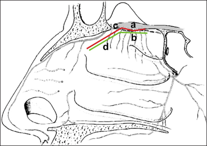
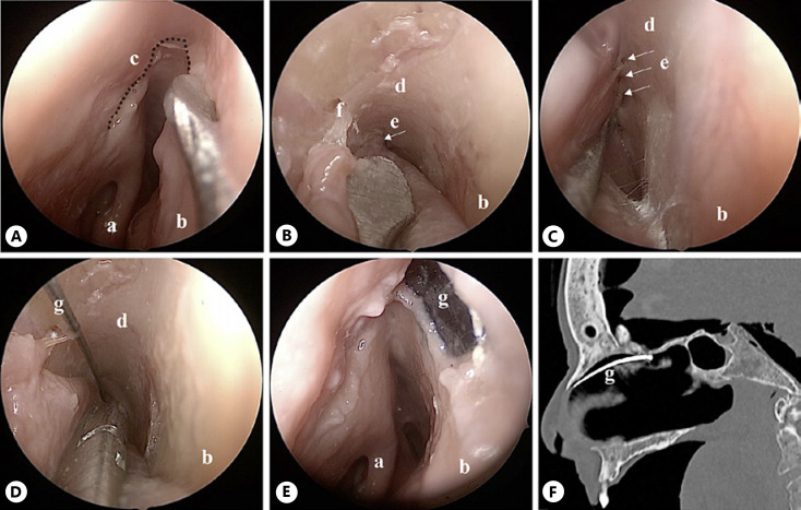
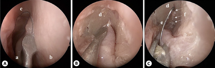
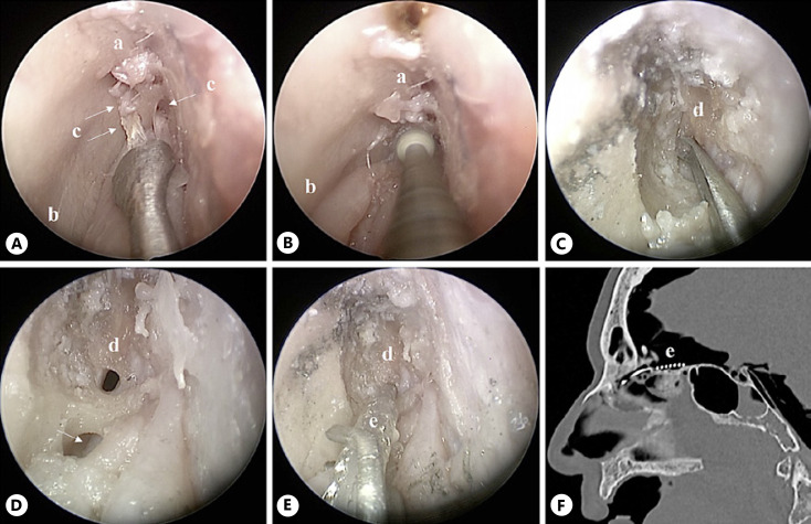
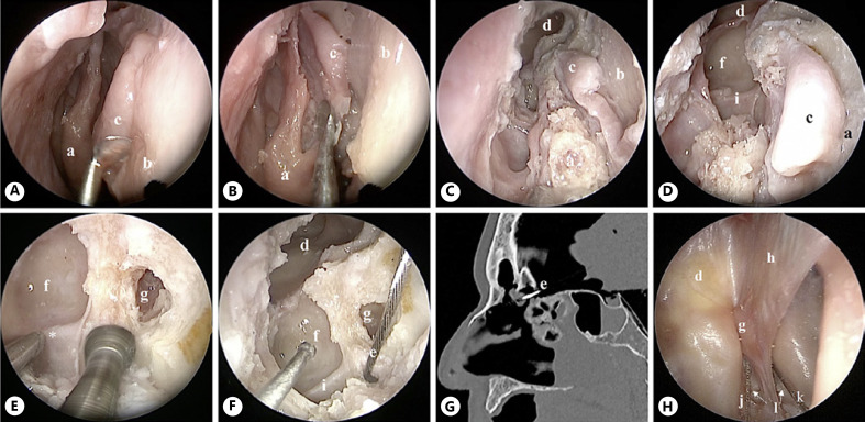
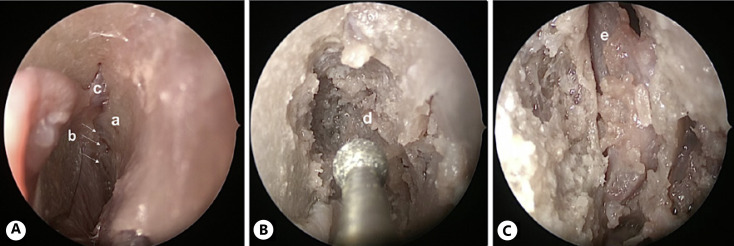
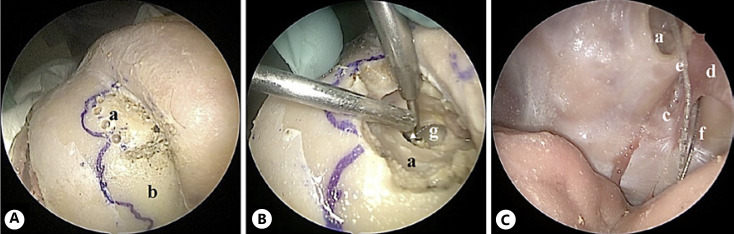
Methods: In a human anatomic cadaver study, we investigated different endoscopic approaches to electrically stimulate the olfactory bulb (OB) based on the following considerations: (1) the stimulating electrode should be close to the OB. (2) The surgical procedure should be as non-invasive and safe as possible and (3) as easy as possible for an experienced ENT surgeon.

Results: In summary, the endoscopic intracranial positioning of the electrode via a widened ostium of the fila olfactoria or a frontal sinus surgery like a Draf IIb procedure is a good option in terms of patients' risk, degree of difficulty for ENT surgeons, and position to the OB. Endoscopic intranasal positioning appeared to be the best option in terms of patient risk and the degree of difficulty for ENT surgeons. Although a bigger approach to the OB using a drill and the combined intranasal endoscopic and external approach enabled a close placement of the electrode to the OB, they do not seem relevant in practice due to their higher invasiveness.

Conclusion: The study suggested that an intranasal positioning of a stimulating electrode is possible, with placements beneath the cribriform plate, extra- or intracranially, applying elegant surgical techniques with low or medium risk to the patient and a close placement to OB.

Keywords: Olfactory dysfunction; Olfactory implant; Sinus surgery; Smell; Surgery.


Conflict of interest statement

The authors have no conflicts of interest to declare.

Figures

Fig. 1
Fig. 1
Schematic representation of the electrical stimulation options of OB. a, OB; b, fila olfactoria; c, red line intracranial position of the stimulator of the OB; d, green line, intranasal position of a stimulator from the inside of the nasal cavity.
Fig. 2
Fig. 2
Endoscopic intranasal positioning of the electrode (approach 1), right nasal fossa. A Harvesting of the U-shaped mucosal flap. B, C Preparing the olfactory cleft as posterior as possible. D The electrode is placed in the olfactory cleft. E The mucosal flap is replaced to cover the electrode so that only a sensor attached to the electrode is seen on endonasal mucosa. F Sagittal CT scan showing a part of the intranasal positioning of the electrode. a, middle turbinate; b, nasal septum; c, dotted line, mucosal incision for the U-shaped flap; d, olfactory cleft; e, fila olfactoria; f, septal branch of anterior ethmoidal artery; g, electrode.
Fig. 3
Fig. 3
Endoscopic intracranial approach through the ostium of the first olfactory fila (approach 2), left nasal fossa. A Harvesting of the U-shaped mucosal flap. B Preparing the olfactory cleft. C The electrode is placed inside the ostium of the first olfactory fila. a, middle turbinate; b, nasal septum; c, mucosal incision for the U-shaped flap; d, olfactory cleft; e, vascular branch; f, fila olfactoria; e, electrode.
Fig. 4
Fig. 4
Endoscopic intracranial approach through the cribriform plate (approach 3), right nasal fossa. A The olfactory cleft is prepared; olfactory fila are cut. B, C The cribriform plate is drilled until the dura is reached. D A small hole in the dura is made. E The electrode is inserted inside the hole. F Sagittal CT scan showing the intracranial positioning of the electrode close to the OB. a, olfactory cleft; b, nasal septum; c, arrows, olfactory fila; d, dura; e, electrode.
Fig. 5
Fig. 5
Endoscopic intracranial approach through Draf IIb procedure (approach 4), right nasal fossa. A Septal flap is harvested and positioned safely medially to the middle turbinate (B). C Draf IIb is performed and first fovea ethmoidalis with AEA are exposed (D). E Drilling of the cribriform plate, medially to the cranial insertion of the common basal lamella and posteriorly to the AEA, until the dura is exposed. F Positioning of the electrode; which will be covered with the septal flap afterward. G Sagittal CT scan showing the intracranial positioning of the electrode. H View from above (a craniotomy was performed with endoscopic assistance) showing the transillumination on the posterior wall of the left frontal sinus and the intracranial placement of the electrodes of approaches 3 and 4. a, middle turbinate; b, nasal septum; c, septal flap; d, frontal sinus; e, electrode; f, first fovea ethmoidalis; g, crista galli; h, falx cerebri; i, anterior ethmoidal artery; j, the electrode of approach 3; k, electrode of approach 4; l, cribriform plate.
Fig. 6
Fig. 6
Endoscopic intracranial approach through the preparation of olfactory cleft (approach 5), left nasal fossa. A The olfactory cleft is prepared; showing olfactory fila and septal branch of anterior ethmoidal artery. B The cribriform plate is drilled until the dura is reached. C Intracranial approach, showing OB. a, olfactory cleft; b, arrows, olfactory fila; c, septal branch of anterior ethmoidal artery; d, dura; e, OB.
Fig. 7
Fig. 7
Combined approach through a frontal osteoplastic flap (approach 6). A The borders of the frontal sinuses are marked in blue on the anterior wall, the left frontal osteoplastic flap is harvested. B Drilling of the frontal sinus posterior wall. C The electrode is inserted through the window created on the frontal sinus posterior wall. a, left frontal sinus; b, right frontal sinus; c, cribriform plate; d, falx cerebri; e, electrode of approach 5; f, electrode of approach 4; g, drilled out posterior wall of left frontal sinus.

Similar articles

Cited by

References

    1. Brämerson A, Johansson L, Ek L, Nordin S, Bende M. Prevalence of olfactory dysfunction the skövde population-based study. Laryngoscope. 2004 Apr;114((4)):733–737. - PubMed
    1. Landis BN, Konnerth CG, Hummel T. A study on the frequency of olfactory dysfunction. Laryngoscope. 2004 Oct;114((10)):1764–1769. - PubMed
    1. Vennemann MM, Hummel T, Berger K. The association between smoking and smell and taste impairment in the general population. J Neurol. 2008 Aug 28;255((8)):1121–1126. - PubMed
    1. Damm M, Temmel A, Welge-Lüssen A, Eckel HE, Kreft MP, Klussmann JP, et al. [Olfactory dysfunctions. Epidemiology and therapy in Germany, Austria and Switzerland] HNO. 2004 Feb 1;52((2)):112–120. - PubMed
    1. Desiato VM, Levy DA, Byun YJ, Nguyen SA, Soler ZM, Schlosser RJ. The prevalence of olfactory dysfunction in the general population a systematic review and meta-analysis. Am J Rhinol Allergy. 2021 Mar 1;35((2)):195–205. - PubMed

Publication types