. 2023 Apr;616(7957):581-589.
doi: 10.1038/s41586-023-05909-9. Epub 2023 Apr 5.

De novo design of modular peptide-binding proteins by superhelical matching

Affiliations

De novo design of modular peptide-binding proteins by superhelical matching

Kejia Wu et al. Nature. 2023 Apr.

Abstract

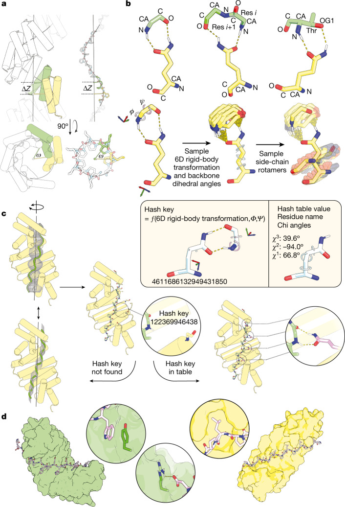
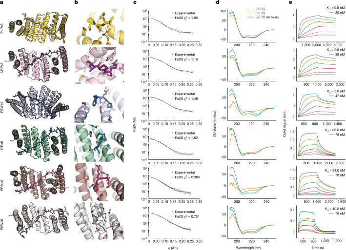
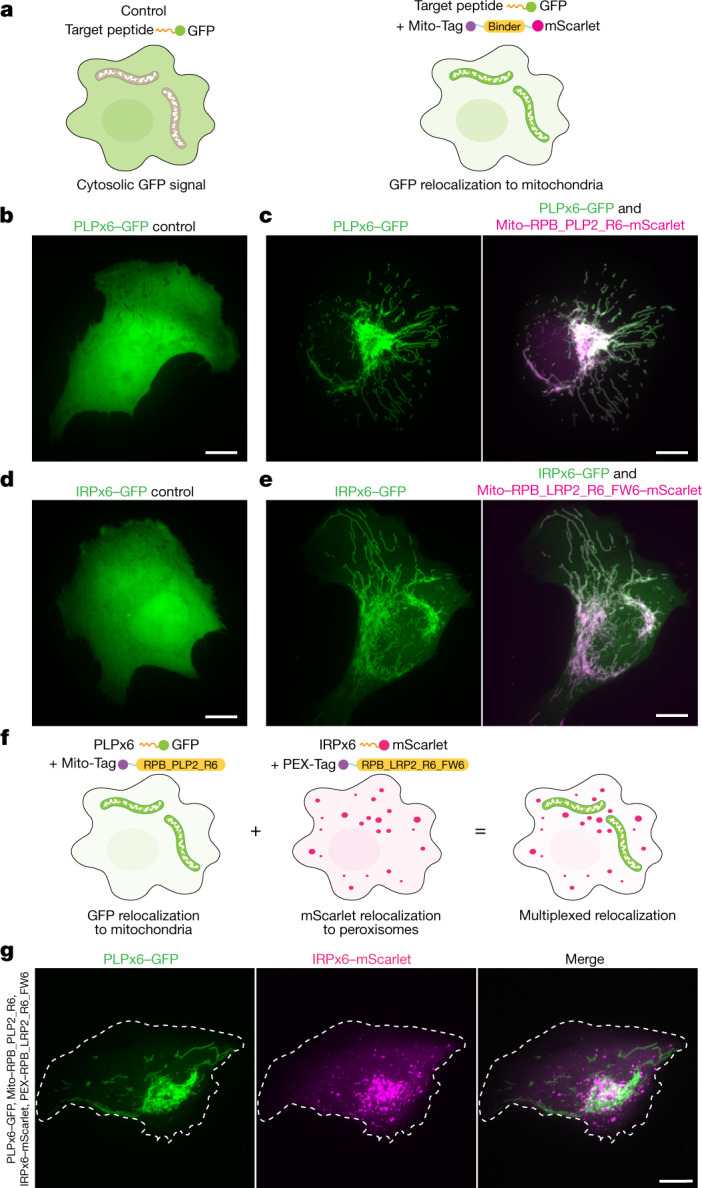
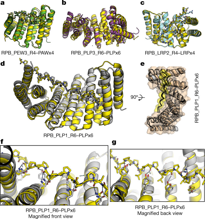
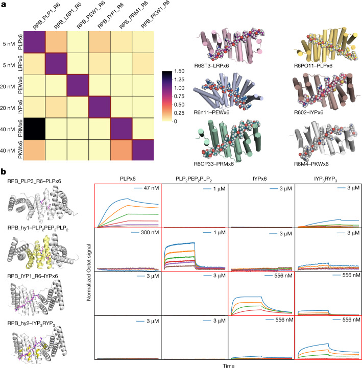
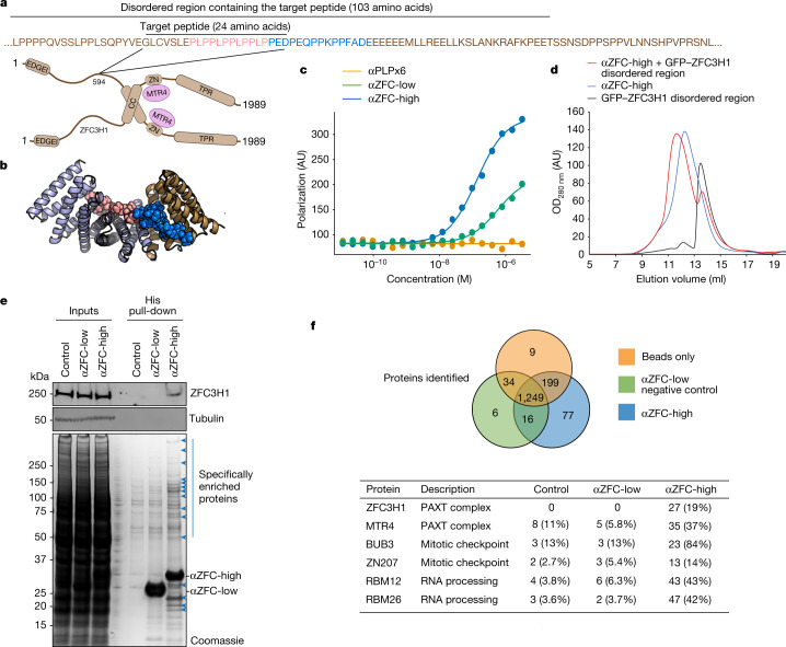
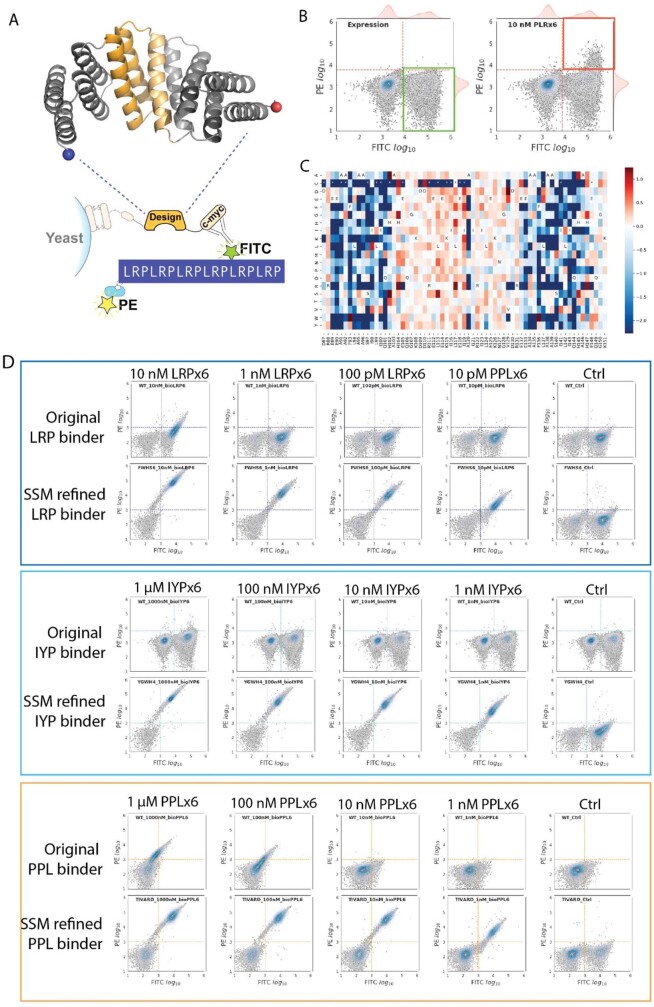
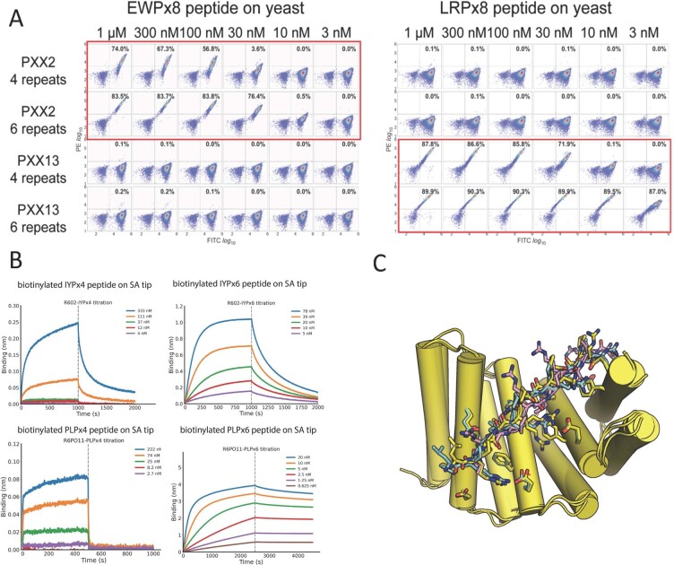
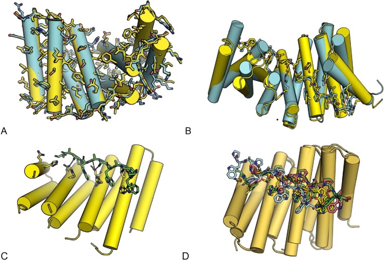
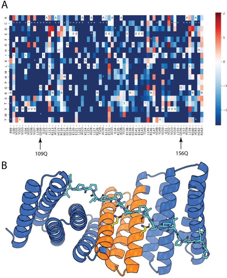
General approaches for designing sequence-specific peptide-binding proteins would have wide utility in proteomics and synthetic biology. However, designing peptide-binding proteins is challenging, as most peptides do not have defined structures in isolation, and hydrogen bonds must be made to the buried polar groups in the peptide backbone1-3. Here, inspired by natural and re-engineered protein-peptide systems4-11, we set out to design proteins made out of repeating units that bind peptides with repeating sequences, with a one-to-one correspondence between the repeat units of the protein and those of the peptide. We use geometric hashing to identify protein backbones and peptide-docking arrangements that are compatible with bidentate hydrogen bonds between the side chains of the protein and the peptide backbone12. The remainder of the protein sequence is then optimized for folding and peptide binding. We design repeat proteins to bind to six different tripeptide-repeat sequences in polyproline II conformations. The proteins are hyperstable and bind to four to six tandem repeats of their tripeptide targets with nanomolar to picomolar affinities in vitro and in living cells. Crystal structures reveal repeating interactions between protein and peptide interactions as designed, including ladders of hydrogen bonds from protein side chains to peptide backbones. By redesigning the binding interfaces of individual repeat units, specificity can be achieved for non-repeating peptide sequences and for disordered regions of native proteins.


Conflict of interest statement

The authors declare no competing interests, except as follows. K.W., H.B., D.R.H., T.J.B., K.E.M., T.J.S., T.E.M., Y.-T.C., R.R., G.B., D.C.E., L.S., E.D., D.A.S., W.S., I.G. and D.B. are co-inventors on a patent application entitled ‘De novo designed modular peptide binding proteins by superhelical matching’ (63/381,109, filed 26 October 2022).

Figures

Fig. 1
Fig. 1. Overview of the procedure for designing modular peptide binders.
a, Like all repeating structures, repeat proteins and peptides form superhelices with constant axial displacement (ΔZ) and angular twist (ω) between adjacent repeat units (shown in green and yellow). For in-register binding, the protein and peptide parameters must match (for some integral multiple of repeat units). b, Construction of hash tables for privileged residue–residue interactions. Top row: classes of side-chain–backbone interactions for which hash tables were built. The side-chain amide group of asparagine or glutamine forms bidentate interactions with the N–H and C=O groups on the backbone of a single residue (left) or consecutive residues (middle), or with the backbone N–H group and side-chain oxygen atom of a serine or threonine residue (right). Second row: as illustrated for the case of the glutamine–backbone bidentate interaction, to build the hash table we perform Monte Carlo sampling over the rigid-body orientation between the terminal amide group and the backbone, and the backbone torsions φ and ψ, saving configurations with low-energy bidentate hydrogen bonds. For each configuration, the possible placements for the backbone of the glutamine are enumerated by growing side-chain rotamers back from the terminal amide. Third row: from the six rigid-body degrees of freedom relating the backbones of the two residues, together with the two φ and ψ torsion angle degrees of freedom, a hash key is calculated using an eight-dimensional hashing scheme. The hash key is then added to the hash table with the side-chain name and torsions as the value. CA, α-carbon; OG, γ-oxygen. c, To dock repeat proteins and repeat peptides with compatible superhelical parameters, their superhelical axes are first aligned, and the repeat peptide is then rotated around and slid along this axis. For each of these docks, for each pair of repeat protein–repeat peptide residues within a threshold distance, the hash key is calculated from the rigid-body transform between backbones and the backbone torsions of the peptide residue, and the hash table is interrogated. If the key is found in the hash table, side chains with the stored identities and torsion angles are installed in the docking interface. d, The sequence of the remainder of the interface is optimized using Rosetta for high-affinity binding. Two representative designed binding complexes are shown to highlight the peptide-binding groove and the shape complementarity. The magnified views illustrate hydrophobic interactions (right), salt bridges (middle) and π–π stacks (left) incorporated during design.
Fig. 2
Fig. 2. Biophysical characterization of designed protein–peptide complexes.
a, Computational models of the designed six-repeat version of protein–peptide complexes. Designed proteins are shown in cartoons and peptides in sticks. b, Magnified views for single designed protein–peptide interaction units. Residues interacting across the interface are shown in sticks. c, Predicted SAXS profiles overlaid on experimental SAXS data points. The scattering vector q is on the x axis (from 0 to 0.25) and the intensity (I) is on the y axis on a logarithmic scale. AU, arbitrary units. d, Circular dichroism (CD) spectra at different temperatures (blue, 20 °C; orange, 95 °C; green, 95 °C followed by 20 °C). e, Bio-layer interferometry characterization of the binding of designed proteins to the corresponding peptide targets. Twofold serial dilutions were tested for each binder and the highest concentration is labelled. The biotinylated target peptides were loaded onto streptavidin biosensors, and incubated with designed binders in solution to measure association and dissociation.
Fig. 3
Fig. 3. Designed binders function in living cells.
a, Experimental design. U2OS cells co-express the target peptide fused to GFP and a fusion between the specific binder fused to mScarlet and a mitochondria-targeting sequence (Mito-Tag). If binding occurs in cells, the GFP signal is relocalized to the mitochondria, whereas control cells that do not express the binder show a cytosolic GFP signal. be, In vivo binding. Live, spreading U2OS cells expressing PLPx6–GFP alone (b), IRPx6–GFP alone (d), PLPx6–GFP and Mito–RPB_PLP2_R6–mScarlet (c) or IRPx6–GFP and Mito–RPB_LRP2_R6_FW6–mScarlet (e) were imaged by spinning disk confocal microscopy (SDCM). Note that the GFP signal is cytosolic in the control but relocalized to the mitochondria after co-expression with the respective binder. f,g, In vivo multiplexing. f, Experimental design. U2OS cells co-express two target peptides, one fused to GFP and the other to mScarlet, and their corresponding specific binder fused to mitochondria- or peroxisome-targeting sequences. If orthogonal binding occurs, GFP and mScarlet signals should not overlap. g, Live, spreading U2OS cells co-expressing PLPx6–GFP, IRPx6–mScarlet, Mito–RPB_PLP2_R6 and PEX–RPB_LRP2_R6_FW6 imaged by SDCM. Note the absence of overlap between channels. Images correspond to maximum intensity z-projections (Δz = 6 µm). Dashed line indicates the cell outline. Scale bars, 10 µm.
Fig. 4
Fig. 4. Evaluation of design accuracy by X-ray crystallography.
ac, Superposition of computational design models (coloured) on experimentally determined crystal structures (yellow). a, RPB_PEW3_R4–PAWx4. b, RPB_PLP3_R6–PLPx6. c, RPB_LRP2_R4–LRPx4. dg, RPB_PLP1_R6–PLPx6, d, Overview of the superimposition of the computational design model and the crystal structure. e, A 90° rotation of d. The complex is shown in surface mode (protein in orange and peptide in yellow) to highlight the shape complementarity. f, Zoom in on the internal three units from d (front view). Glutamine residues from the protein in both the design and the crystal structure are shown as sticks to highlight the accuracy of the designed side-chain-to-backbone bidentate ladder. g. View from the side opposite to f. Tyrosine residues from the protein in both the design and the crystal structure are shown as sticks to highlight the accuracy of the designed polar interactions.
Fig. 5
Fig. 5. Designed protein–peptide interaction specificity.
a, Left, to assess the cross-reactivity of each designed peptide binder in Fig. 2 with each target peptide, biotinylated target peptides were loaded onto bio-layer interferometry streptavidin sensors and allowed to equilibrate, and the baseline signal was set to zero. The bio-layer interferometry tips were then placed into a solution containing proteins at the indicated concentrations for 500 s and washed with buffer, and dissociation was monitored for another 500 s. The heat map shows the maximum signal for each binder–target pair (cognate and non-cognate) normalized by the maximum signal of the cognate designed binder–target pair. Right, surface shape complementarity of the cognate complexes. The peptides are in sphere representation. b, Modular pocket sequence redesign generates binders for peptide sequences that are not strictly repeating. Left, ribbon diagrams of base designs (rows 1 and 3) and versions with a matching subset of the protein and peptide modules redesigned. The ribbon diagrams show the cognate designed and redesigned assemblies; for example, the first row shows a six-repeat PLP binding design in complex with PLPx6, and the second row the same backbone with repeat units 3 and 4 redesigned to bind PEP instead of PLP, in complex with a PLP2PEP2PLP2 peptide. The redesigned peptide and protein residues are shown in purple sticks and yellow, respectively. Right, orthogonality matrix. Biotinylated target peptides were loaded onto biosensors, and incubated with designed binders in solution at the indicated concentrations. Red rectangle boxes indicate cognate complexes. Octet signal was normalized by the maximum signal of the cognate designed binder–target pair.
Fig. 6
Fig. 6. Design of binders to disordered regions of endogenous human proteins.
a, Schematic model of the human PAXT complex composed of a heterotetramer of ZFC3H1 and MTR4. CC, coiled-coil domain; ZN, Zn-finger domain. Inset shows the sequence environment of the target sequence. b, Surface shape complementarity between the target peptide from ZFC3H1 (sphere) and the highest-affinity cognate binder, αZFC-high. c, Fluorescence polarization binding curves between the indicated ZFC3H1 binders and the target ZFC3H1 peptide (PLP)4PEDPEQPPKPP. As a negative control, we used the (PLP)x6 binder, RPB_PLP3_R6 (see Fig. 4). αZFC-high shows a higher binding affinity to the target peptide than αZFC-low, in contrast with RPB_PLP3_R6, which shows negligible binding. d, Superdex 200 10/300 GL SEC profiles of purified αZFC-high, a fusion between GFP and a 103-amino-acid fragment of the disordered region of ZFC3H1 containing the target sequence (see a), or a 1:1 mix of the two after two hours of incubation. OD280 nm, optical density at 280 nm. e, Top, HeLa cell extracts were subjected to pull-down using the indicated binders bound to Ni-NTA agarose beads, or naked beads as a control. Recovered proteins were processed for western blot against endogenous ZFC3H1 (or tubulin as a loading control). Bottom, Coomassie-stained SDS–PAGE gel of the samples analysed at the top. These panels are representative of n = 3 experiments. f, Proteomic analysis of the His-pull-down samples shown in e. Top, overlap between the proteins identified, setting a threshold of five peptides for correct identification. Bottom, examples of proteins identified (number indicates exclusive peptide count; protein coverage is indicated in parentheses). See Source Data for the full dataset. For gel source data, see Supplementary Fig. 1. Source Data
Extended Data Fig. 1
Extended Data Fig. 1. Examples of computationally designed model geometry and convergence of backbone docking.
ac, Examples of repeat proteins computationally designed to bind to extended beta strand (a), polypeptide II (b) and helical peptide backbones (c). d, Monte Carlo flexible backbone docking calculations after design to assess the structural specificity of the designed peptide-binding interface. It started from large numbers of peptide conformations randomly generated with superhelical parameters in the range of those of the proteins (usually 10,000–50,000 trajectories), and selected those designs with converged peptide backbones (RMSD < 2.0 among the top 20 designs with lowest DDG) close to the design model (RMSD < 1.5). Green dots shown in the above example plot represent the converged designs picked by this threshold.
Extended Data Fig. 2
Extended Data Fig. 2. Comparison of binding affinities from freshly made and 30-day-old samples, and mitochondria immunostainings in control U2OS cells.
a, Little decrease in binding observed for designs RPB_PLP1_R6 and RPB_PEW1_R6 30-day-old in 4 °C. Bio-layer interferometry characterization of binding of designed proteins to the corresponding peptide targets. Twofold serial dilutions were tested for each binder, and the full tested concentration is labelled. The biotinylated target peptides were loaded onto the streptavidin (SA) biosensors, and incubated with designed binders in solution to measure association and dissociation. b, Mitochondria immunostainings in control U2OS cells. Wild-type U2OS cells were spread onto fibronectin coverslips as in Fig. 3, then fixed and processed for immunofluorescence using TOM20 antibodies as a marker of mitochondria. Note that mitochondria appearance in these control cells is similar to that observed upon overexpression of designed binders fused to mitochondria-targeting sequences (Fig. 3). suggesting that these constructs do not affect mitochondria shape. Scale bar, 10 µm.
Extended Data Fig. 3
Extended Data Fig. 3. SSMs libraries are constructed and screened for enhancing the peptide-binding abilities of designed repeat-peptide binders.
a, A schematic illustration of the mutagenesis region within the designed repeat protein, and the principles of the yeast surface display assay for peptide binding analysis. In short, the biotinylated repeat peptides (a six-repeat of LRP peptide is shown as an example) are synthesized and can be detected by SAPE, while the expression of designed protein on yeast surface are monitored by FITC-conjugated anti-Myc antibody. A double high signal of both PE and FITC, using flow cytometry, indicates the valid peptide-binding events. b, The SSM libraries are first subjected to expression sorting (left), in which there is no targeted peptide added. The yeast populations, which display well expressed SSM mutants, will show above threshold FITC signals, are collected (green box) for next-generation sequencing, and are regrown for the next rounds of sorting. In the next round sorting, the targeted peptide is incubated with the yeast library, and labelled by both FITC and SAPE (right). The FITC+PE+ population is collected for analysis (orange box). c, By using next-generation sequencing, enrichment analysis for each mutation is carried out, and a heat map for all mutations is generated. In this heat map, using a designed LRP binder SSM library as an example, the red shades indicate enrichment with incubating with the targeted peptide, and the blue shades indicate depletion. Several mutations show exceptional enhancement of the LRP repeat peptide-binding ability, such as F93W, H102S and others. d, Using the SSM library, we can markedly enhance the peptide-binding abilities of the designed peptide binder. Three example yeast display assays titrating the peptide concentrations are shown here. The top row of each example is using the originally designed peptide binder, and the bottom row is using the peptide binder containing the combinations of the best mutations discovered in the SSM library screenings. An approximately 1,000-fold increase of the peptide-binding ability can be achieved with the assistance of SSM libraries. Note, the ratio of yeast population in the upper right quadrant indicates the peptide-binding ability.
Extended Data Fig. 4
Extended Data Fig. 4. Comparison of binding affinities when changing repeat numbers from either binder or peptide side. and top five flexible backbone docks for the four-repeat LRP binder RPB_LRP2_R4–LRPx4.
a, Six-repeat versions of RPB_LRP2_R6 and RPB_PEW2_R6 had higher affinity for eight-repeat LRP and PEW peptides than four-repeat versions without any decrease in specificity in yeast surface display. Biotinylated repeat proteins (the six-repeat versions RPB_LRP2_R6 and RPB_PEW2_R6 and the four-repeat versions RPB_LRP2_R4 and RPB_PEW2_R4) were detected by SAPE, and the expression of the designed repeat peptide on yeast surface was monitored by FITC-conjugated anti-Myc antibody. Serial dilutions were tested for each binder, and the full tested concentration is labelled. b, Six-repeat IYP and PLP peptides had higher affinity for six-repeat versions of the cognate designed repeat proteins (RPB_IYP1_R6 and RPB_PLP1_R6) than four-repeat versions by bio-layer interferometry. The full tested concentration is labelled. The biotinylated target peptides were loaded onto the streptavidin (SA) biosensors, and incubated with designed binders in solution to measure association and dissociation. The dissociation rate was markedly increased when testing against the six-repeat peptides as compared to the four-repeat peptides, indicating a much tighter binding event. c, Top five complex PDBs for RPB_LRP2_R4–LRPx4 from the flexible docking generated ensemble. Green, pink and grey are the ones closest to the crystal structure (shown in yellow) with RMSD over the peptide and the binding residues ≈ 0.03 Å, whereas the cyan dock RMSD = 3.89 Å.
Extended Data Fig. 5
Extended Data Fig. 5. Crystal structures of the unbound RPB_LRP2_R4, bound RPB_PLP3_R6–PLPx6 and bound RPB_PEW3_R4 and its top five flexible backbone docks.
a, Crystal structure of the unbound first-round design RPB_LRP2_R4 (yellow) aligned with the design model (cyan). b, Crystal structure of the first-round complex RPB_PLP3_R6–PLPx6 (yellow) aligned with the design model (cyan). As is shown here, the peptide PLP units fit exactly into the designed curved groove formed by repeating tyrosine, alanine and tryptophan residues matching the design model with near atomic accuracy, with Cα RMSD of 1.70 Å for the binder apo, 2.00 Å for the peptide neighbour interface and 1.64 Å for the whole complex. c, Co-crystal structure of RPB_PEW3_R4–PAWx4. The PAW units bind to a relatively flat groove formed by repeating histidine residues and glutamine residues as designed (shown as sticks). d, Top five complex PDBs for RPB_PEW3_R4–PAWx4 from the flexible docking generated ensemble. Green, pink and grey are the ones closest to the crystal structure (shown in yellow) with RMSD over the peptide and the binding residues ≈ 0.03 Å, whereas the cyan dock RMSD = 3.89 Å.
Extended Data Fig. 6
Extended Data Fig. 6. SSM binding interface footprinting results were consistent with the design model and crystal structure.
a, Using a PPL repeat-peptide binder as an example, a heat map presenting enrichment analysis for each mutation is generated. In each cell, the red colour indicates enrichment, and the blue colour indicates depletion. Wild-type sequences are indicated in the cells labelled with amino-acid one-letter codes. The mutants missing in the expression library are labelled with asterisks. Two positions (109Q and 156Q) are highlighted as examples showing conserved positions. Almost all mutations other than the wild type in these two positions are greatly depleted. b, Illustration shows the SSM region (orange), and the two conserved positions (109Q and 156Q in yellow).
Extended Data Fig. 7
Extended Data Fig. 7. Characterization of ZFC3H1 binders.
a, Bio-layer interferometry screening for the seven endogenous ZFC3H1 binders. Twofold serial dilutions were tested for each binder, and the full tested concentration is labelled. The biotinylated target 24-amino-acid peptides (PLPPLPPLPPLPPEDPEQPPKPPF) were loaded onto the streptavidin (SA) biosensors, and incubated with designed binders in solution to measure association and dissociation. The two tightest binders (αZFC_93 and αZFC_97, renamed αZFC-high and αZFC-low, respectively) were selected for further fluorescence polarization characterization and cell assays. b, Characterization of ZFC3H1 binders for pull-down of endogenous target: Hela cell extracts were subjected to pull-down using the indicated binders bound to Ni-NTA agarose beads, or naked beads as control. Recovered proteins were processed for western blot against endogenous ZFC3H1 (or tubulin as a loading control). Two completely independent experiments are shown. These experiments are repeats of the experiment presented in Fig. 6e, albeit at a different salt concentration, namely 50 mM instead of 150 mM. For gel source data, see Supplementary Fig. 1.

References

    1. London N, Movshovitz-Attias D, Schueler-Furman O. The structural basis of peptide–protein binding strategies. Structure. 2010;18:188–199. doi: 10.1016/j.str.2009.11.012. - DOI - PubMed
    1. Neduva V, et al. Systematic discovery of new recognition peptides mediating protein interaction networks. PLoS Biol. 2005;3:e405. doi: 10.1371/journal.pbio.0030405. - DOI - PMC - PubMed
    1. Neduva V, Russell RB. Peptides mediating interaction networks: new leads at last. Curr. Opin. Biotechnol. 2006;17:465–471. doi: 10.1016/j.copbio.2006.08.002. - DOI - PubMed
    1. Ernst P, Plückthun A. Advances in the design and engineering of peptide-binding repeat proteins. Biol. Chem. 2017;398:23–29. doi: 10.1515/hsz-2016-0233. - DOI - PubMed
    1. Andrade, M. A., Petosa, C., O’Donoghue, S. I., Müller, C. W. & Bork, P. Comparison of ARM and HEAT protein repeats. J. Mol. Biol.309, 1–18 (2001). - PubMed

Publication types