. 2023 Apr;39(2):1637-1652.
doi: 10.1109/tro.2022.3220973. Epub 2022 Nov 23.

Design, Control, and Experimental Evaluation of A Novel Robotic Glove System for Patients with Brachial Plexus Injuries

Affiliations

Design, Control, and Experimental Evaluation of A Novel Robotic Glove System for Patients with Brachial Plexus Injuries

Wenda Xu et al. IEEE Trans Robot. 2023 Apr.

Abstract

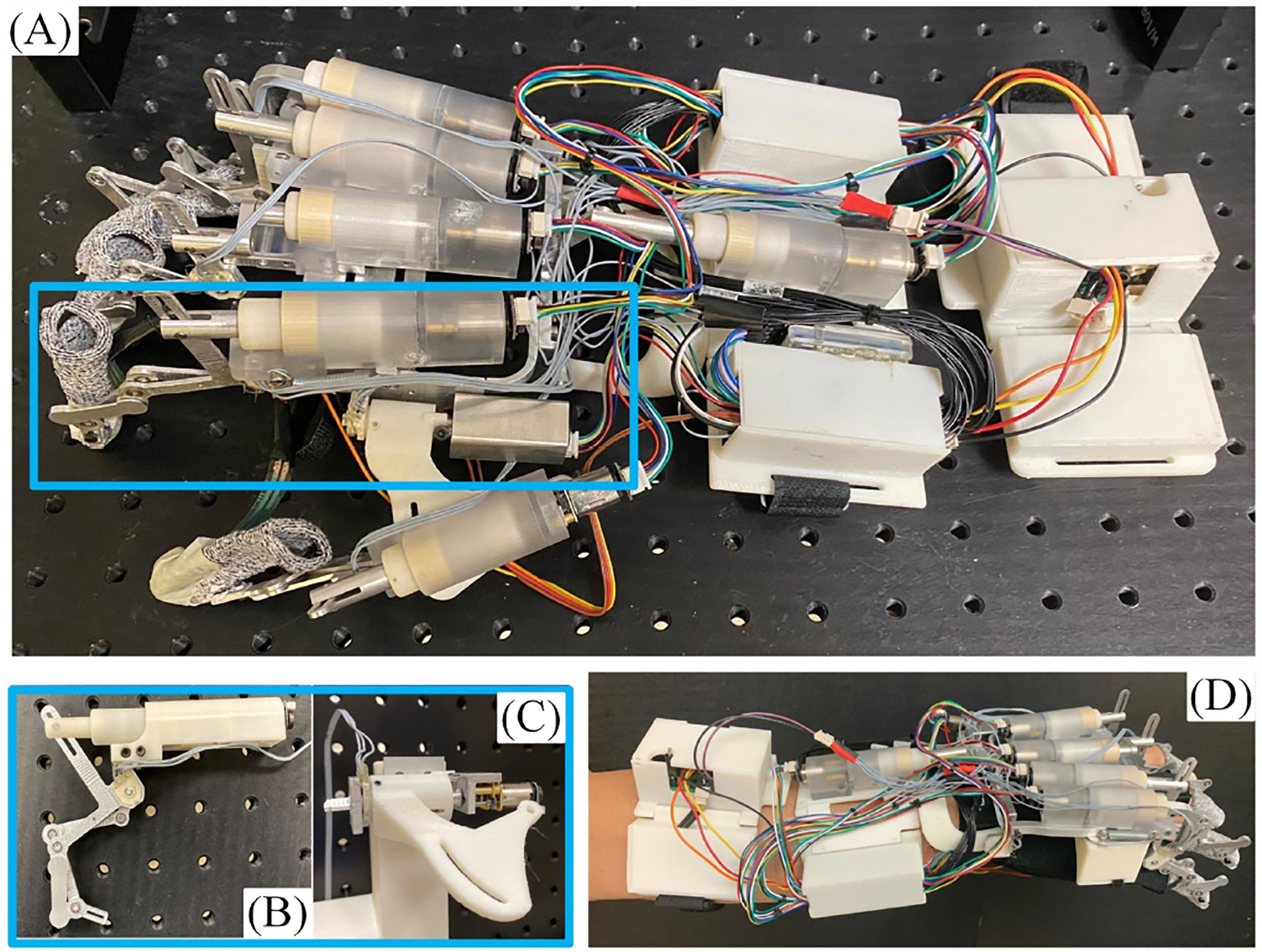
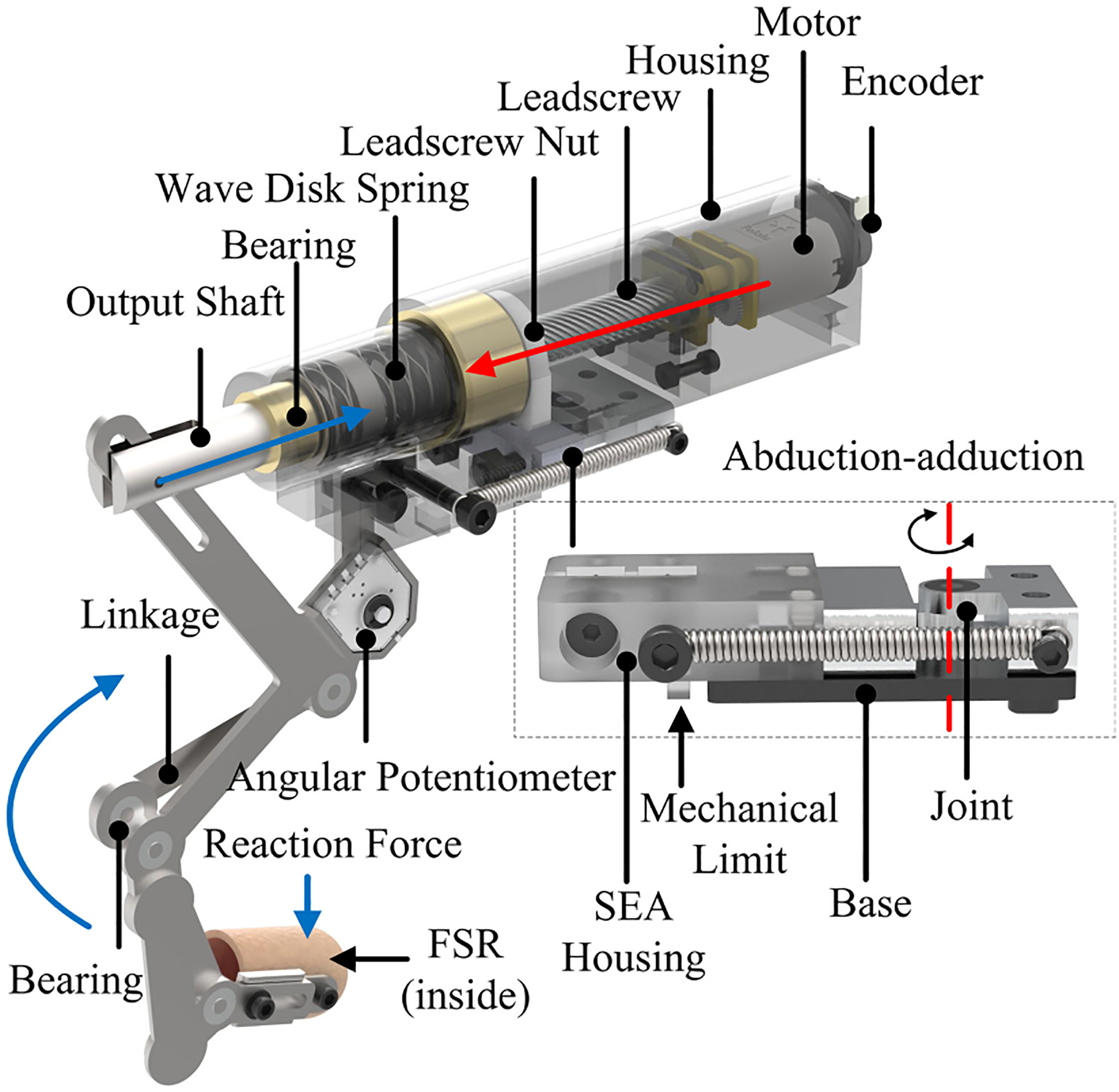
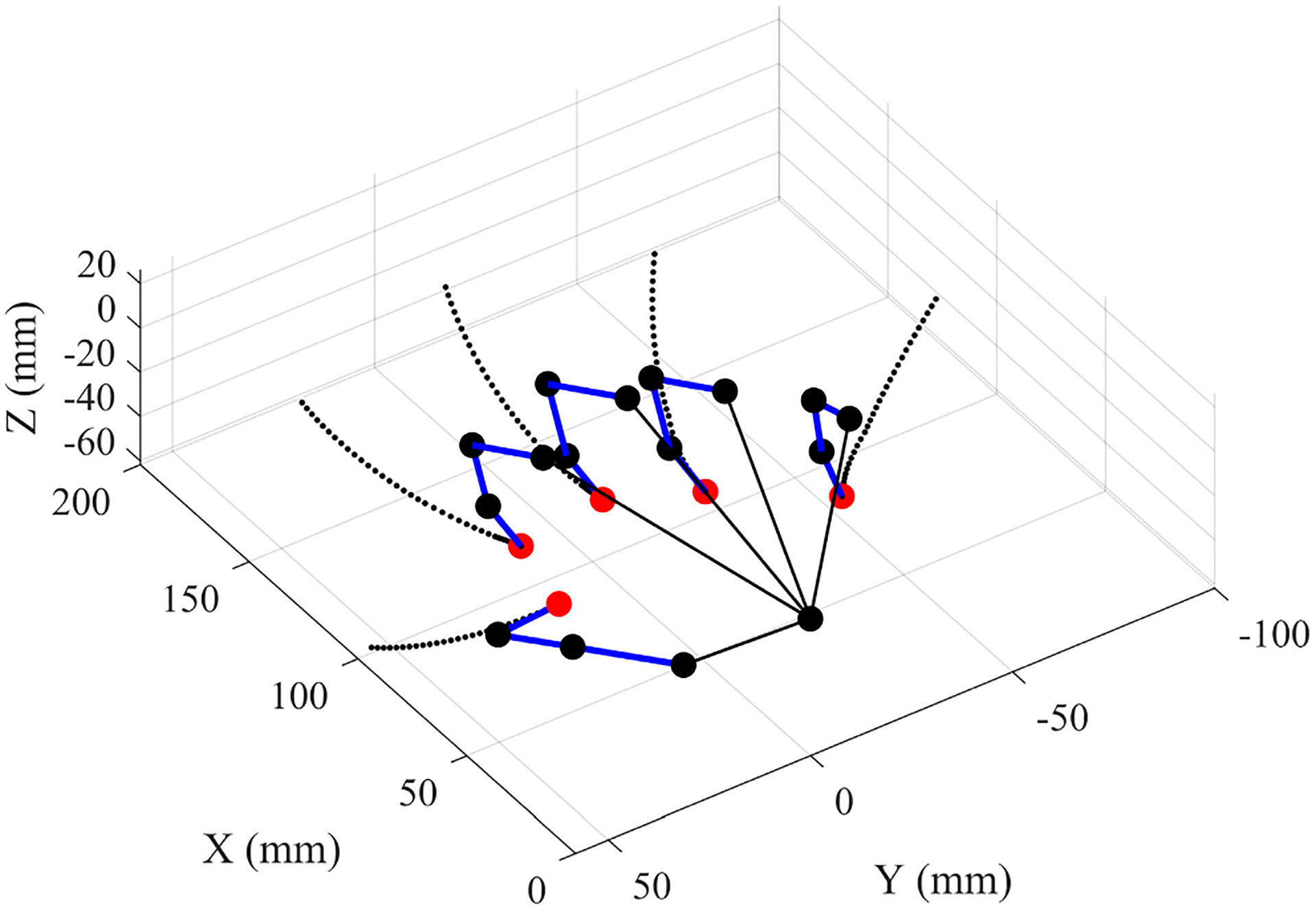
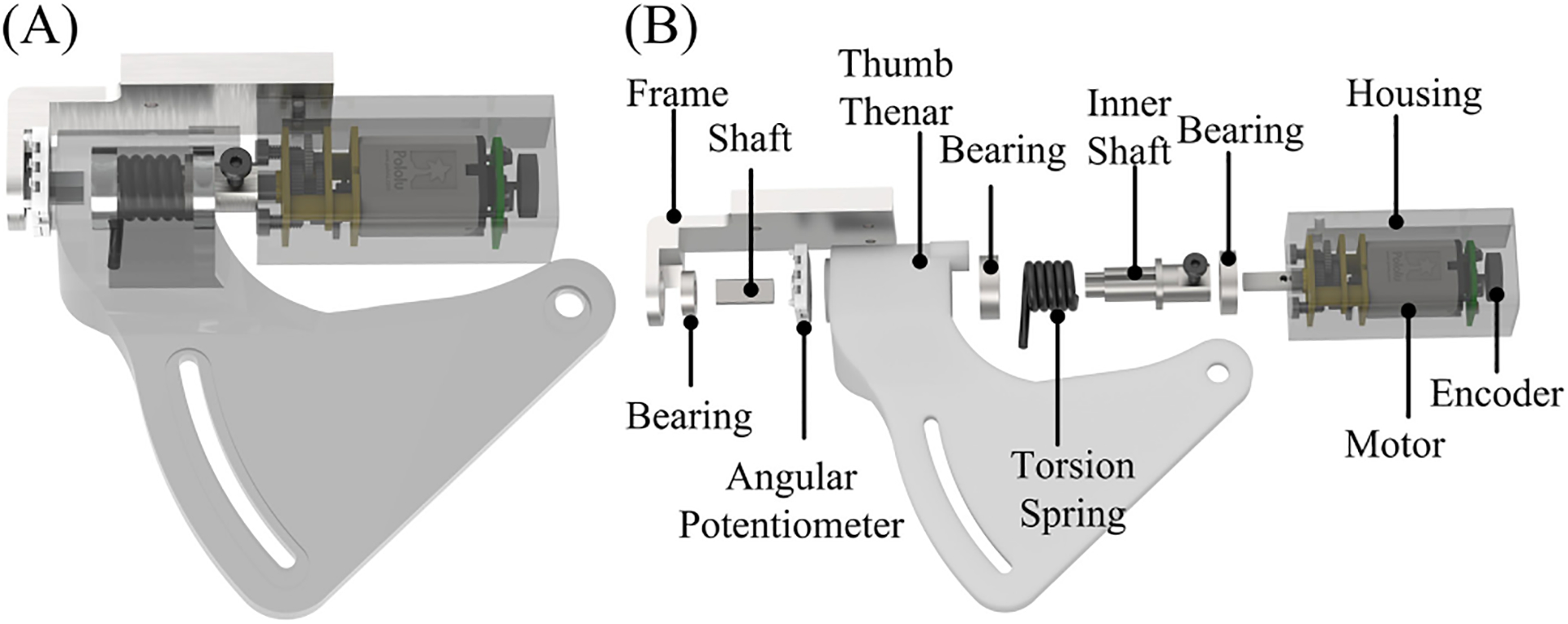
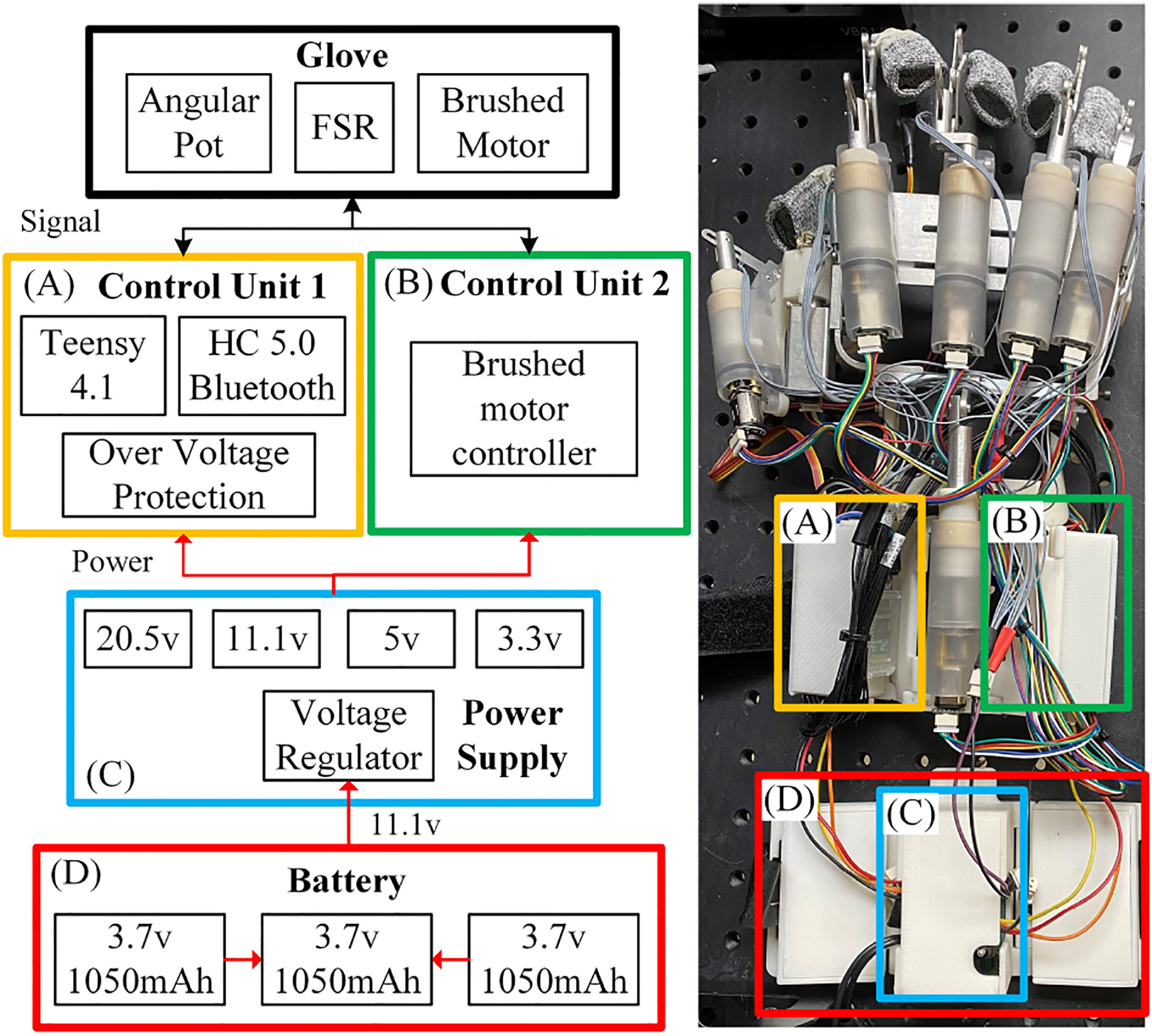
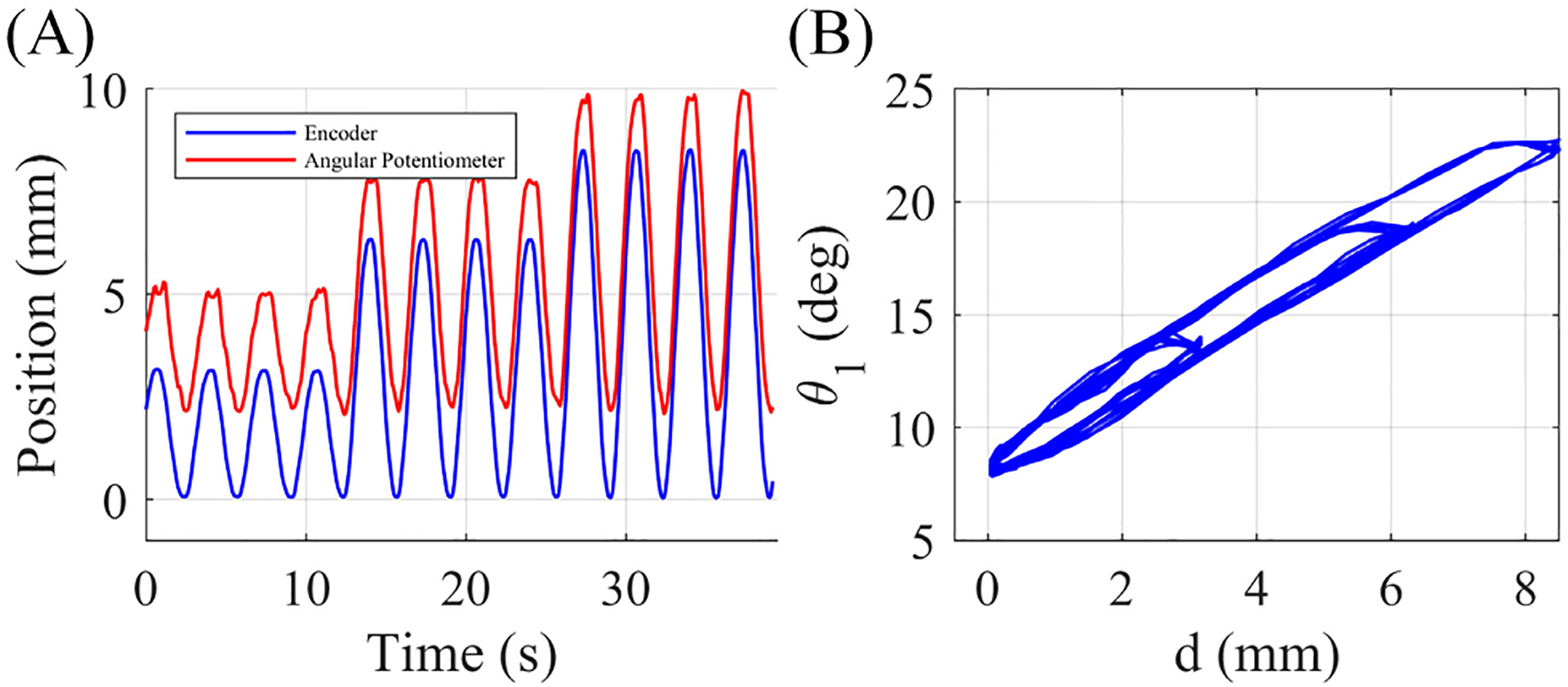
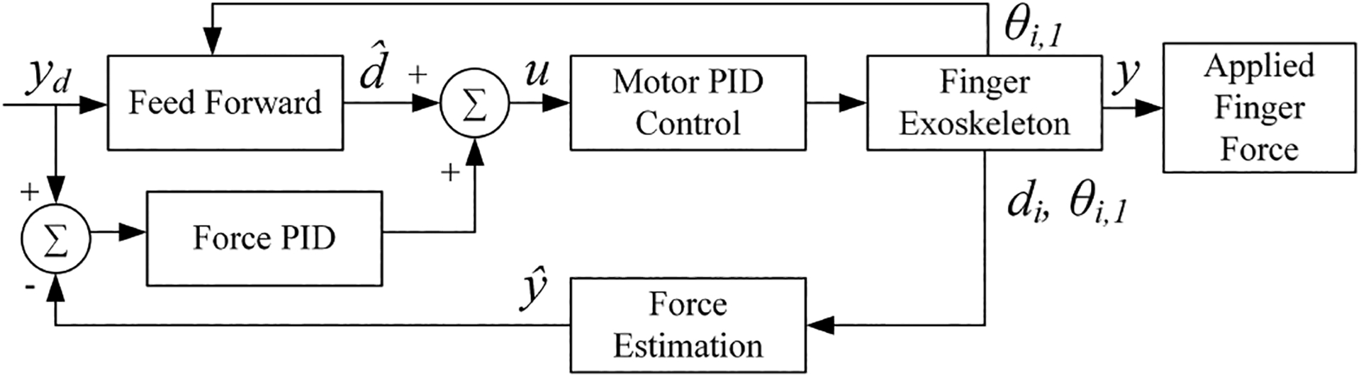
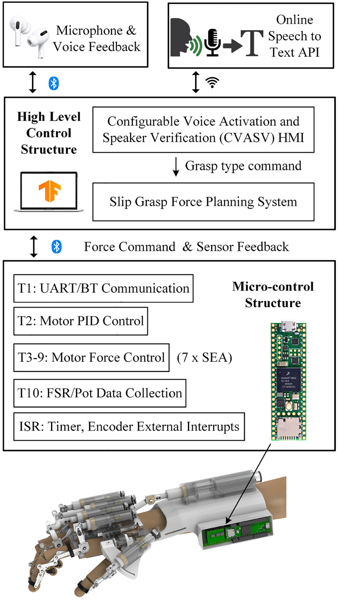
This paper presents the development of an exoskeleton glove system for people who suffer from brachial plexus injuries, aiming to assist their lost grasping functionality. The robotic system consists of a portable glove system and an embedded controller. The glove system consists of Linear Series Elastic Actuators (LSEA), Rotary Series Elastic Actuators (RSEA), and optimized finger linkages to provide imitated human motion to each finger and a coupled motion of the hand. The design principles and optimization strategies were investigated to balance functionality, portability, and stability. The model-based force control strategy compensated with a backlash model and model-free force control strategy are presented and compared. Results show that our proposed model-free control method achieves the goal of accurate force control. Finally, experiments were conducted with the prototype of the developed integrated exoskeleton glove system. Results from 3 subjects with 150 trials show that our proposed exoskeleton glove system has the potential to be used as a rehabilitation device for patients.

Keywords: Exoskeleton Glove; grasp assistance; series elastic actuator; wearable robotics.


Figures

Fig. 1.
Fig. 1.
(A) overview of the exoskeleton glove system, (B) index finger linear Series Elastic Actuators (SEA), (C) rotary SEA, (D) user wearing the exoskeleton glove. Blue – enlarged view of index finger linear SEA and rotary SEA.
Fig. 2.
Fig. 2.
Mechanism schematic and kinematic model of the index exoskeleton finger linkage. Different colors represent different links: Blue link – Distal phalanx, Green link – Intermediate phalanx, Orange link – Proximal phalanx, Brown links – constraint links.
Fig. 3.
Fig. 3.
Perspective View of the index linkage. The screw nut guided by leadscrew connects to the output shaft. The compressed wave disk spring between the output shaft and screw nut measures the force by its deformation when the fingertip makes contact with an object. The red arrow shows the force generation flow and the blue arrow shows the force measurement flow. The distal link is adjustable and can be extended by 7mm. The LSEA can slide on the base to accommodate different hand size. The partial view shows the details of the abduction-adduction mechanism. It is implemented at the bottom of the SEA to connect the finger linkage with the base through a joint. At the initial position, the hand needs to be open and be ready for grasping. The spring on the side pulls the exoskeleton finger linkage to the side to perform the abduction. Mechanical limits were added to avoid excess force to the fingers. The palmar interossei muscle group will perform the adduction automatically and stretch the spring while grasping.
Fig. 4.
Fig. 4.
Kinematic simulation of the optimized index finger exoskeleton rotating around the MCP joint from 5° to 35°. The trajectories of the PIP joint, DIP joint, and fingertip are shown. The referenced trajectories, which are based on the referenced joint angle with a selected finger length, are also shown for comparison.
Fig. 5.
Fig. 5.
Simulation of a small diameter cylindrical grasp with optimized finger linkages. The blue bars represent the exoskeleton links. The black dots represent the exoskeleton joints. The red dots represent the endpoints of each linkage. The dotted lines represent the trajectories of the fingers’ motion.
Fig. 6.
Fig. 6.
Design of RSEA for thumb thenar: (A) Perspective view of the RSEA, (B) Exploded view of the RSEA.
Fig. 7.
Fig. 7.
Electronics design overview: (A) micro-controller board, (B) brushed motor controller board, (C) power conversion board, (D) 3-in-1 battery package.
Fig. 8.
Fig. 8.
Backlash illustration. (A) The motor position calculated by encoder and angular potentiometer separately, (B) The relationship between the motor position d and the MCP joint angle θ1.
Fig. 9.
Fig. 9.
Force control scheme for a single exoskeleton finger. θi,1 represents the MCP joints of exoskeleton finger i (i ∈ {1, 2, 3, 4, 5}). di represents the current motor position of exoskeleton finger i.
Fig. 10.
Fig. 10.
Illustration of the control software architecture.
Fig. 11.
Fig. 11.
Test platform with different load cell mounting positions. (A) load cell is mounted horizontally. (B) load cell is mounted vertically.
Fig. 12.
Fig. 12.
(A) The LSEA motor position trajectory with load cell horizontal installation (θ1 = 12°). (B) The LSEA motor position trajectory with load cell vertical installation (θ1 = 25°).
Fig. 13.
Fig. 13.
(A) Force measurement with load cell horizontal installation (θ1 = 12°). (B) Force measurement with load cell vertical installation (θ1 = 25°).
Fig. 14.
Fig. 14.
(A) The comparison between the estimation of motor current position and measurement from encoder. (B) The comparison between the estimation of motor current position and measurement from encoder, related to MCP joint angle θ1.
Fig. 15.
Fig. 15.
Force prediction results on training dataset with different θ1 configurations. Each configuration is performed twice in sequential order. Different configurations are not time related.
Fig. 16.
Fig. 16.
Force prediction results on test dataset with different θ1 configurations. Each configuration is performed once. Different configurations are not time related.
Fig. 17.
Fig. 17.
The comparison of MSE on training dataset and test dataset, and active features number with different highest polynomial order.
Fig. 18.
Fig. 18.
The comparison of MSE on training dataset and test dataset, and active features number with different λy value.
Fig. 19.
Fig. 19.
Results on training dataset with different θ1 configurations.
Fig. 20.
Fig. 20.
Results on test dataset with different θ1 configurations.
Fig. 21.
Fig. 21.
Results of motor position prediction on training dataset with different θ1 configurations. Each configuration has 2 sets of data. The x-axis represents the sample number which is put in time order. Different sets of data are not time related.
Fig. 22.
Fig. 22.
Results of motor position prediction on test dataset with different θ1 configurations. Each configuration has 1 set of data. The x-axis represents the sample number which is put in time order. Different sets of data are not time related.
Fig. 23.
Fig. 23.
The comparison between desired force, measured force and generated force. (A) shows the experimental results on horizontal platform (θ1 = 14.9°) and (B) shows the experimental results on vertical platform (θ1 = 21°).
Fig. 24.
Fig. 24.
Examples of successful grasps of each object. Each object is grasped 5 times by a single participant. (A) bottle, (B) jar, (C) screw driver, (D) ball, (E) tape, (F) small box, (G) pen, (H) small ball, (I) flat box, (J) bowl.
Fig. 25.
Fig. 25.
The experiment results for each objects. The flat box and bowl is hard to grasp since the lateral grasp is hard to be performed with insufficient DOF of thumb linkage.

Similar articles

Cited by

References

    1. Brault MW, Americans with disabilities: 2010. US Department of Commerce, Economics and Statistics Administration, US, 2012.
    1. Midha R, “Epidemiology of Brachial Plexus Injuries in a Multitrauma Population,” Neurosurgery, no. June, pp. 1182–1189, 1997. - PubMed
    1. Park HR, Lee GS, Kim IS, and Chang J-C, “Brachial Plexus Injury in Adults,” The Nerve, vol. 3, no. 1, pp. 1–11, 2017.
    1. Giuffre JL, Kakar S, Bishop AT, Spinner RJ, and Shin AY, “Current Concepts of the Treatment of Adult Brachial Plexus Injuries,” Journal of Hand Surgery, vol. 35, no. 4, pp. 678–688, 4 2010. - PubMed
    1. Bos RA, Haarman CJ, Stortelder T, Nizamis K, Herder JL, Stienen AH, and Plettenburg DH, “A structured overview of trends and technologies used in dynamic hand orthoses,” Journal of NeuroEngineering and Rehabilitation, vol. 13, no. 1, pp. 1–25, 2016. - PMC - PubMed

LinkOut - more resources