Review
. 2023 May 2;59(36):5312-5328.
doi: 10.1039/d3cc00573a.

Recent advances in single-cell subcellular sampling

Affiliations
Review

Recent advances in single-cell subcellular sampling

Annie Sahota et al. Chem Commun (Camb). .

Abstract

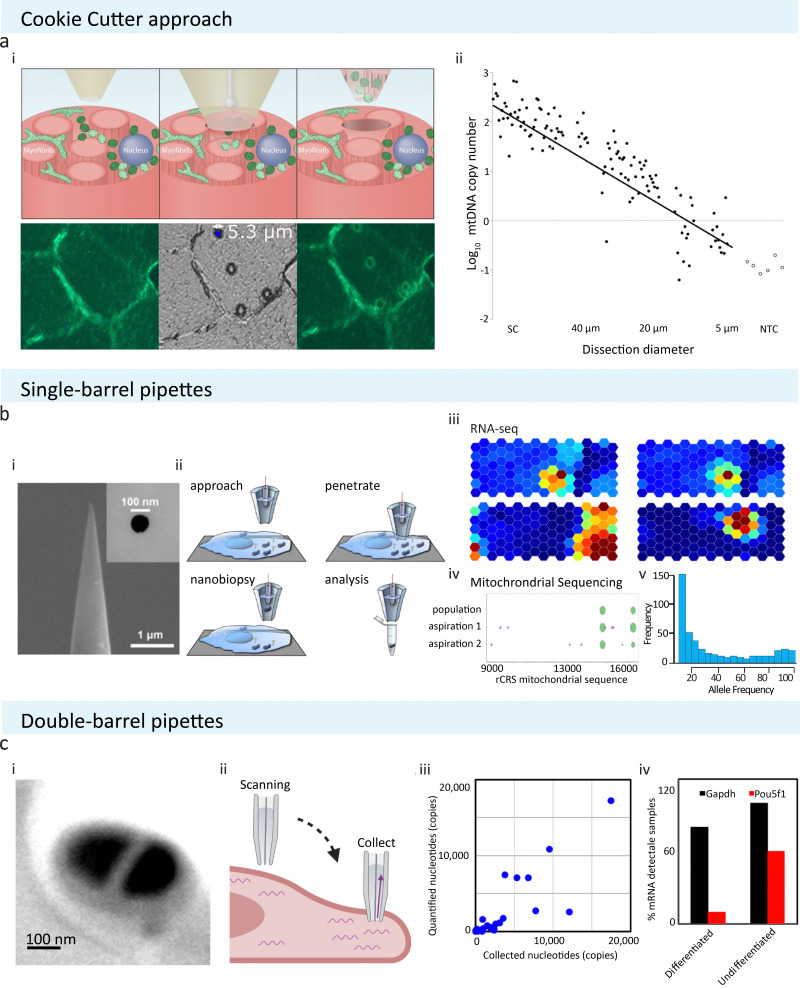
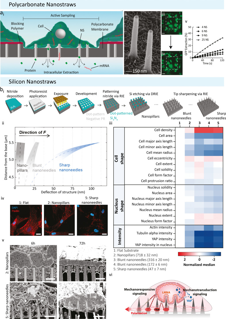
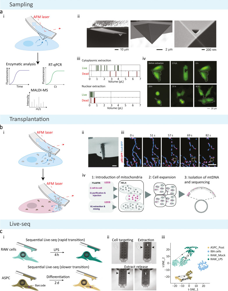
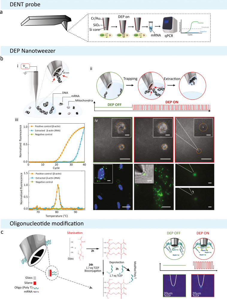
Recent innovations in single-cell technologies have opened up exciting possibilities for profiling the omics of individual cells. Minimally invasive analysis tools that probe and remove the contents of living cells enable cells to remain in their standard microenvironment with little impact on their viability. This negates the requirement of lysing cells to access their contents, an advancement from previous single-cell manipulation methods. These novel methods have the potential to be used for dynamic studies on single cells, with many already providing high intracellular spatial resolution. In this article, we highlight key technological advances that aim to remove the contents of living cells for downstream analysis. Recent applications of these techniques are reviewed, along with their current limitations. We also propose recommendations for expanding the scope of these technologies to achieve comprehensive single-cell tracking in the future, anticipating the discovery of subcellular mechanisms and novel therapeutic targets and treatments, ultimately transforming the fields of spatial transcriptomics and personalised medicine.


Conflict of interest statement

There are no conflicts of interest to declare.

Figures

Fig. 1
Fig. 1. Schematic of pipette-based cellular sampling technologies and downstream analysis. (a) The ‘cookie cutter’ approach from Bury et al. extracts cellular content by plunging through tissue sections. (i) Localised cellular samples are removed alongside with the micropipette after puncturing. (ii) The number of samples obtained is depends on the pore size used; with a pipette of 5 μm in size, a single mitochondrion could be extracted. Reproduced from ref. . Copyright 2022, Springer Nature. (b) Single-barrel pipettes from Actis et al. could be used to extract cellular samples with or without SICM. (i) SEM image of a typical single barrel with tip size of 100 nm or below are commonly utilised in extracting localised cellular samples. Reprinted (adapted) with permission from ref. . Copyright 2014, American Chemical Society. (ii) A schematic showing the experimental procedure of nanobiopsy when combined with SICM to obtain cellular topography. (iii) and (iv) Extracted samples have been analysed using RNA-seq, mitochondrial sequencing, or RT-qPCR to study cell-to-cell variability or single cell mitochondrial heterogeneity. Reproduced with permission from ref. , (Copyright 2018, Elsevier), and (Copyright 2017, Elsevier). (c) Double-barrel pipettes used in combination with SICM to obtain cellular contents at precise locations. (i) SEM image shows a typical dual barrel pipette applied for SICM-nanobiopsy. (ii) During SICM-single-cell biopsy, one of the two barrels of the pipette was used to acquire cell topography via SICM, and then sample extraction was done by exerting negative pressure to aspirate cellular fluid at the desired cellular location. (iii) The amount of transcripts detectable via RT-qPCR is proportional to the amount of samples collected. (iv) The dual barrel pipettes have been used to obtain subcellular amounts of samples from stem cells and study the differentiation status of stem cells by analysing differentiation marker Pou5f1 in mouse embryonic stem cells. Reprinted (adapted) from ref. . Copyright 2016, American Chemical Society. The schematic was created with BioRender.com.
Fig. 2
Fig. 2. Nanostraw use adapted from Cao et al. and Seong et al. (a) Polycarbonate nanostraws adapted from Cao et al. (i) Polycarbonate nanostraws allow intracellular species within the cell to diffuse through the NS and into the extraction buffer below the membrane. The size of the sampling region can be defined lithographically so that only the cells that grow in the active regions are sampled. (ii) Tilted view (45°) SEM image of the 150 nm diameter NS. (iii) and (iv) Fluorescent microscopy images of GFP of a culture of 26 cells on a 200 × 200 μm NS sampling region (white dashed squares, scale bar = 50 μm). (iii) GFP-expressing CHO cells before sampling. (iv) GFP-expressing CHO cells immediately after sampling. Locally diminished GFP intensities (dark spots) were observed in the cells after sampling, corresponding to the locations where GFP was removed from the cells. Brightness was increased to highlight the spots. (v) The percentage of the cell's initial GFP that diffuses into the extraction buffer as a function of time and the number of NS (the dashed line indicates the GFP extraction level after 2 min of diffusion from six NS). Reproduced from ref. . Copyright 2017, National Academy of Sciences. (B) Size-Tunable silicon based Nanostraws reported by Seong et al. (i) Schematic detailing the photolithography and dry silicon etching processes. Silicon nitride was deposited as a hard mask onto a silicon wafer, dot arrays of photoresist were patterned on the nitride layer by photolithography, silicon nitride, unprotected by photoresist was reactive ion etched (RIE), nanopillar arrays were produced via deep reactive ion etching (DRIE), and sharpened into nanoneedle arrays. (ii) Deflection of nanopillars (Dtip = 718 ± 32 nm), blunt nanoneedles (Dtip = 316 ± 20 nm), and sharp nanoneedles (Dtip = 47 ± 7 nm) when 300 nN of traction force (F) was imposed at the apex of each structure. Note that only the upper 1.5 μm of tip deflection is shown, as this is the region in which the deflection profiles differ the most. (iii) Normalized heatmap showing the change in population median on different substrates for a selected range of parameters. Note: data shown here are transformed and normalized to flat substrates; hence ‘1’ is blank (white). (iv) Representative confocal immunofluorescence images of paxillin-stained focal adhesions in hMSCs on different structures after 24 h of culture, scale bars = 25 μm. (v) Visualization of nuclear membrane–structure interfaces using FIB-SEM. FIB-SEM images show the extent of plasma membrane and nuclear envelope deformation after 6 h and 72 h of culture on nanopillars (Dtip = 718 ± 32 nm) and sharp nanoneedles (Dtip = 47 ± 7 nm), respectively (scale bars = 2 μm). Reproduced from ref. . Copyright 2020, American Chemical Society.
Fig. 3
Fig. 3. Schematic of FluidFM methodologies. (a) Basic FluidFM sampling consists of an AFM cantilever with a continuous pressure-driven channel. (i) A pyramidal tip with a triangular aperture is inserted into a cell, and negative pressure is applied to aspirate the contents of the cell for downstream analysis. (ii) Scanning electron micrographs of the FluidFM probe for cellular sampling. (iii) Cell viability as a function of FluidFM extraction volumes from the cytoplasm and nucleus, where each line represents one count. The dashed line indicates the median, dotted lines represent the minimum and maximum native volumes. (iv) Fluorescent time-lapse imaging of an extracted cell (2.9 pL removed from the cytoplasm using FluidFM), marked with a dashed line. The extracted cell behaved similarly to the adjacent non-extracted cell, where they became round and divided to produce daughter cells at the same time. Reproduced with permission from ref. . Copyright 2016, Elsevier. (b) Mitochondrial transplantation from one cell to another is achieved with a cylindrical probe and a larger aperture size. (i) Following aspiration of mitochondria from the host cell, the probe is inserted into a new cell, and positive pressure is applied to inject the host's mitochondria. (ii) Scanning electron microscopy image of the cylindrical probe used for combining extraction and injection of mitochondria (scale bar = 2 μm). (iii) Time-lapse imaging of mitochondria and mitochondrial nucleoid extraction, showing an overlay of the mitochondrial matrix (su9-BFP) and mitochondrial nucleoids (p55-GFP), where the yellow box illustrates the position of the cantilever (scale bar = 5 μm). (iv) Procedure for quantifying mtDNA uptake and maintenance after transplantation, illustrating two FluidFM transplantation methods (cell-to-cell transplantation and injection of purified mitochondria), and the control performed for non-specific uptake (mixing with extracted donor cell mitochondria). Reproduced from ref. . Copyright 2022, PLOS. (c) FluidFM extraction is combined with Smartseq2 technology to form Live-seq: sequential transcriptomic profiling of live single cells. (i) Sequential sampling was performed in a rapid (top) and slow (bottom) cell state transition, where a unique barcode was used in the 3′ untranslated region of a green fluorescent protein reporter to identify the same cell over longer time periods. (ii) Images of the Live-seq sampling procedure using FluidFM, where the black arrows show the level of buffer and extract inside the probe, and the white arrows represent the under- or over-pressure applied. (iii) Direct trajectories of sequentially sampled cells from projections of Live-seq data. Reproduced from ref. . Copyright 2022, Springer Nature.
Fig. 4
Fig. 4. DEP based subcellular sampling techniques. (a) Schematic of a modified AFM probe with DENT. Created with BioRender.com. (b) DEP Nanotweezer schematic showing how DNA can be extracted from a live cell: (i) application of an a.c. voltage on the nanotweezer generates a highly localized electric field gradient suitable for targeted molecular trapping in solution or inside a cell. (ii) Step-by-step schematics of a single cell biopsy. The tip was approached and then inserted into the cell nucleus; the application of an a.c. bias traps DNA molecules at the nanotweezer tip, and, in the final step, the nanotweezer along with the accumulated material was withdrawn from the cell. (iv) Biopsies were also performed in cells stained with a non-specific RNA dye (SYTO RNASelect). The accumulation of labelled mRNA during DEP capture results in an increase in fluorescence at the nanotweezer tip (left and middle). The mRNA can still be seen at the tip once extracted from the cell (right, scale bars = 20 μm, insets = 5 μm). (v) Targeted mRNA trapping and extraction was performed by labelling, via in situ hybridization, of individual ETS-1 mRNA molecules with fluorescein isothiocyanate (green dots) (left). A high-resolution fluorescence image of individual ETS-1 mRNA molecules (middle) along with a superimposed bright-field image is shown (inset). The application of the a.c. voltage resulted in trapping of mRNA at the nanotweezer tip (top right), which was then pulled away by the subsequent withdrawal of the nanotweezers, causing a drop in the fluorescence signal (bottom right). Scale bars: left, 25 μm (inset, 5 μm); middle, 10 μm (inset, 2 μm); right, 1 μm. Reproduced from ref. . (c) Updated nanotweezer system with its glass surface modified to contain an RNA Trap Poly Thymine Oligomer sequence on the tip. Modifying the surface of the glass with a broadly binding oligomer was attempted to increase the overall amount of mRNA that can be held by a single trapping event. The modification was done using click chemistry to bind the oligomer to the glass surface depicted on the left. On the right is a diagrammatic representation of the modified nanotweezers trapping free-flowing mRNA in solution. Alexa Fluor 488 labelled mRNA was extracted from MCF-7 cancer cells and diluted in 100 mM KCl. The corresponding heatmaps show the tips of the nanotweezers before and after DEP was induced.

References

    1. Borland L. M. Kottegoda S. Phillips K. S. Allbritton N. L. Annu. Rev. Anal. Chem. 2008;1:191–227. doi: 10.1146/annurev.anchem.1.031207.113100. - DOI - PubMed
    1. Wang F. Flanagan J. Su N. Wang L. C. Bui S. Nielson A. Wu X. Vo H. T. Ma X. J. Luo Y. J. Mol. Diagn. 2012;14:22–29. doi: 10.1016/j.jmoldx.2011.08.002. - DOI - PMC - PubMed
    1. Vu T. Vallmitjana A. Gu J. La K. Xu Q. Flores J. Zimak J. Shiu J. Hosohama L. Wu J. Douglas C. Waterman M. L. Ganesan A. Hedde P. N. Gratton E. Zhao W. Nat. Commun. 2022;13:169. doi: 10.1038/s41467-021-27798-0. - DOI - PMC - PubMed
    1. Chen K. H. Boettiger A. N. Moffitt J. R. Wang S. Zhuang X. Science. 2015;348:aaa6090. doi: 10.1126/science.aaa6090. - DOI - PMC - PubMed
    1. Chan K. L. A. Fale P. L. V. Atharawi A. Wehbe K. Cinque G. Anal. Bioanal. Chem. 2018;410:6477–6487. doi: 10.1007/s00216-018-1245-x. - DOI - PMC - PubMed