

Review
doi: 10.3390/jcm12072522.
Clinical Utility of Three-Dimensional Echocardiography in the Evaluation of Mitral Valve Disease: Tips and Tricks
Affiliations
- PMID: 37048605
- PMCID: PMC10094963
- DOI: 10.3390/jcm12072522
Item in Clipboard
Review
Clinical Utility of Three-Dimensional Echocardiography in the Evaluation of Mitral Valve Disease: Tips and Tricks
J Clin Med.
.
Abstract
Although real-time 3D echocardiography (RT3DE) has only been introduced in the last decades, its use still needs to be improved since it is a time-consuming and operator-dependent technique and acquiring a good quality data can be difficult. Moreover, the additive value of this important diagnostic tool still needs to be wholly appreciated in clinical practice. This review aims at explaining how, why, and when performing RT3DE is useful in clinical practice.
Keywords: echocardiography; mitral valve disease; three-dimensional.
Conflict of interest statement
The authors declare no conflict of interest.
Figures

Tridimensional transthoracic echocardiography (3D-TTE) quality (left panel) compared with three-dimensional transesophageal echocardiography (3D-TEE) (right panel). Both images show an LA view of MV prolapse with a P1 flail (yellow arrow) in a patient with Barlow disease. 3D-TEE allows a more refined representation of the morphological alterations and the ruptured chords compared with 3D-TTE.

MV endocarditis in a patient with Barlow disease. (A) X-plane modality simultaneously shows the long axis and the commissural views: vegetation on the posterior leaflet is visualized. (B) The 3D-zoom modality allows the identification of two different vegetations on A1 and P1 scallops. (C) Full volume modality allows a more detailed anatomical characterization of filamentous-like vegetation on scallop A1 and of the polypoid vegetation on scallop P1. (D) Color 3D modality shows a main regurgitation jet originating from A1-P1 scallops and a minor jet originating from the P2 scallop. MV: mitral valve.
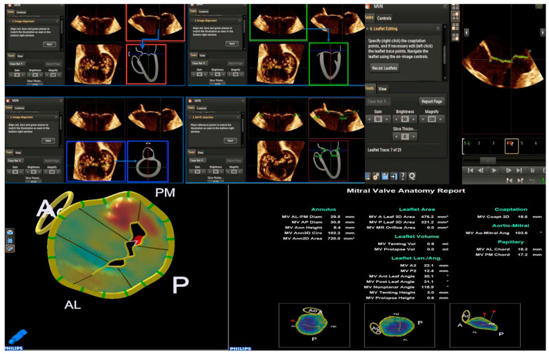
The control panel of the MVN is shown. The various parameters obtained by MVN are displayed on the bottom right. Each step is explained in the text. MVN: mitral valve navigation.
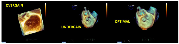
Acute endocarditis of MV in a patient with a previous surgical mitral repair. The sequence of 3D-zoomed images acquired with different gain settings is shown. The left image is noisy because of the overgained acquisition; the central image offers a low resolution of the cardiac structures because of the undergained acquisition; the right image is the optimal one, and the vegetation on the mitral annuloplasty suture is well assessed using the optimal gain setting. MV: mitral valve.

A 3D full volume acquisition of a P3 prolapse and chordal rupture of PMC. (A) MPR: longitudinal plane (red line), transversal plane (blue line), and sagittal plane are positioned perpendicularly at the region of interest (prolapse). (B) Icrop modality: after the correct alignment of the planes, the box crop is moved toward the region of interest, and the resulting image is displayed on the bottom right. (C) The 3D image obtained can be rotated to obtain the best perspective (360°), such as in an LA view or (D) in an LV view. PMC: posteromedial commissure; MPR: multiplanar reconstruction; LA: left atrial; LV: left ventricular.

Cropped angled views of A3 prolapse due to chordal rupture of the PMC. (A) AV in the upper position: this view allows the optimal identification of the anterior leaflet. (B) AV in lateral position: this view allows the optimal analysis of AMC. (C) AV in the medial position: this view allows the optimal analysis of PMC. (D) AV in a lower position allows the optimal analysis of the posterior leaflet. The (B–D) images clearly detect the rupture of the chordae of the PMC but not the (A) image. PMC: posteromedial commissure; AV: aortic valve; AMC: anterolateral commissure.

A case of complex Barlow disease. (A) MPR and cropped image of A2–P2 prolapse. (B) LA view of the RT3DE rendered image after the cropping reveals the partition of the scallops A2 and P2 in subscallops and a cleft (*) between P2 and P3. (C) RT3DE color Doppler allows the identification of the eccentric regurgitant jet at the level of the PMC. (D) A more refined RT3DE rendered image permits clear identification of a cleft between P2 and P3 (arrow) and clearly shows the PMC prolapse. This figure shows how the different RT3DE modalities can add different diagnostic information. MPR: multiplanar reconstruction; PMC: posteromedial commissure.

Panel with figures (A–C) represents the power of RT3DE anatomical characterization (A,C) to localize the vegetation (arrow) and its pathological repercussion (RT3DE color strongly underlines the eccentric jet of regurgitation). Panel with figures (D–F) shows the ability of 3DAC to refine the form, the size, and the position of the vegetation. 3DAC: three-dimensional anatomical characterization.

A case of MV papillary rupture complication of myocardial infarction. (A) MPR and very eccentric RT3DE cropped images depict a ruptured chord (yellow arrow). (B) RT3DE cropped images allow distinguishing of the ruptured head of the papillary muscle hanging on the posterior MV leaflet and prolapsing in the left atrium (red arrow). (C) A further ruptured chord can be seen in the left atrium (red arrow). MV: mitral valve; MPR: multiplanar reconstruction. MV: mitral valve; MPR: multiplanar reconstruction.

Panel (A), a case of FED. Panel (B), a case of BD. The two panels represent the typical report of MVN for the two different etiologies. The height and volume of MV prolapse are the main MVN parameters differentiating the etiologies. See the text for the cut-off values. FED: fibroelastic deficiency; BD: Barlow disease; MVN: mitral valve navigation; MV: mitral valve.

A case of eccentric MV regurgitation. The 3D TTE color Doppler allows the estimation of the ERO and RV by the measurement of the 3D-VCA. 3D-TTE: three-dimensional transthoracic echocardiography; ERO: effective regurgitant orifice; VR: regurgitation volume; 3D-VCA: three-dimensional vena contracta area. 3D-PISA: three-dimensional-proximal isovelocity surface area.

3D-TTE of a moderate MV regurgitation. By moving the planes perpendicularly to the tips of MV, MPR allows the reconstruction of the regurgitant mitral orifice, and its area can be measured with more precision 3D-TTE: three-dimensional transthoracic echocardiography; MPR: multiplanar reconstruction. ERO = Effective Regurgitant Orifice.

(A–D). 3D-TTE of a mild MV stenosis. (B) 3D-TEE of a severe MV stenosis. (B–D). By moving the planes perpendicularly to the tips of MV, multiplanar reconstruction (MPR) allows the reconstruction of the stenotic mitral orifice, and its area can be measured with more precision.

(A) 3D-TEE color cropping in a case of mitral regurgitation with multiple jets. In the MPR modality, the jets are preliminarily intersected perpendicularly and are successively cropped (a white box in the figure is placed on the jets). On the top right, the RT3DE cropped image shows the multiple regurgitation jets (the main at the level of A2-P2) from LA view. (B) 3D-TEE power color map of multiple jet regurgitation. An LA view shows an eccentric jet on the bottom left. On the bottom right, an LV view shows a multiple jet regurgitation. The LV view allows locating the flow convergence (jet origin) with more precision. 3D-TEE: three-dimensional transesophageal echocardiography; LA: left atrial; LV: left ventricular; MPR: multiplanar reconstruction.

3D-TEE of BD with flail valve. On the left the panel are displayed different angled LA views showing the involvement of both leaflets; however, the anterior leaflet presents a more extensive myxomatous degeneration with respect to the posterior leaflet, and the A1 scallop flail can be detected. The right figure represents a zoomed RT3DE rendered image of two clefts of the posterior leaflet (red arrows). BD: Barlow disease; LA: left atrial.

A case of type IIIa degenerative senile and TLMAC MV regurgitation. (A,B) 2D-TEE focused on mitral valve apparatus. Dual plane (left) shows fibrosis of leaflets and extensive annular calcification. Regurgitant jet originating from mitral leaflets (right) is depicted. (C,D): 3D-TEE reconstruction of the mitral valve. The left atrial view is represented in the classical surgeon’s view (left). Omogeneus posterior annular calcification appears as a protuberance undistinguishable from other structures; the low frame rate does not permit precise tissue characterization. A ventricular view is presented (right). Irregular calcifications involving subvalvular apparatus are distinguishable from other cardiac structures. 2D-TTE: two-dimensional trans-thoracic echocardiography; 2D-TEE: two-dimensional transesophageal echocardiography; LA: left atrial; LV: left ventricular; PMC: posteromedial commissure; ALC: anterolateral commissure; MV: mitral valve; TLMAC: tumor-like mitral annular calcification.

(1) Secondary MV regurgitation by symmetric tethering of both leaflets. (Panel A). MV cropping, MV rendered image, and cropped RT3DE color modality are shown. Multiple regurgitant jets are well detected by RT3DE color, and from an LV view, the precise localization of the flow convergence can be appreciated (A2-P2 and A3-P3). (Panel B) MVN of the MV. The tenting height (8.6 mm) is diagnostic of symmetric tethering, and its value is important for the suitability of percutaneous MV repair. In this patient, two clips were implanted. MV: mitral valve; LV: left ventricular; MVN: mitral valve navigation. (2) Ischemic MV regurgitation by tethering of the posterior leaflet (asymmetric regurgitation). (Panel A) 2D TTE, APICAL longitudinal VIEW for LVOT clearly shows the tethering of the posterior leaflet by the scarred LV posterior wall and the pseudo-prolapse of the anterior leaflet with the resultant eccentric jet (left). 2D-TTE, apical 2 chamber view, the inferior wall aneurysm is well defined and two regurgitant jets are detected (right). (Panel B) MVN obtained by 3D-TEE does not show an important tenting height. MV: mitral valve; TTE: trans-thoracic echocardiography; LVOT: left ventricular outflow tract; MVN: mitral valve navigation; 3D-TEE: three-dimensional transesophageal echocardiography.

(1) Secondary MV regurgitation by symmetric tethering of both leaflets. (Panel A). MV cropping, MV rendered image, and cropped RT3DE color modality are shown. Multiple regurgitant jets are well detected by RT3DE color, and from an LV view, the precise localization of the flow convergence can be appreciated (A2-P2 and A3-P3). (Panel B) MVN of the MV. The tenting height (8.6 mm) is diagnostic of symmetric tethering, and its value is important for the suitability of percutaneous MV repair. In this patient, two clips were implanted. MV: mitral valve; LV: left ventricular; MVN: mitral valve navigation. (2) Ischemic MV regurgitation by tethering of the posterior leaflet (asymmetric regurgitation). (Panel A) 2D TTE, APICAL longitudinal VIEW for LVOT clearly shows the tethering of the posterior leaflet by the scarred LV posterior wall and the pseudo-prolapse of the anterior leaflet with the resultant eccentric jet (left). 2D-TTE, apical 2 chamber view, the inferior wall aneurysm is well defined and two regurgitant jets are detected (right). (Panel B) MVN obtained by 3D-TEE does not show an important tenting height. MV: mitral valve; TTE: trans-thoracic echocardiography; LVOT: left ventricular outflow tract; MVN: mitral valve navigation; 3D-TEE: three-dimensional transesophageal echocardiography.
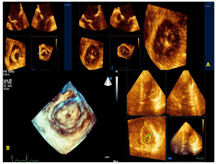
Mitral valve Stenosis. (Panel A) 3D-TEE. A greater MV area is measured for the incorrect position of the blue plane placed on the plane orthogonal to the mitral valve orifice (left). In the central figure, the correct position of the blue plane is shown. The correct position of the plane allows the proper representation of the MV orifice allowing the correct measurement of the planimetric area (right). (Panel B) 3D-TTE LV view of MV stenosis (left, Clip 5). The MPR of the MV area is performed at the level of the tips of the leaflets (right). Transthoracic imaging offers suboptimal imaging. MV: mitral valve; MPR: multiplanar reconstruction; 3D-TTE: three-dimensional transthoracic echocardiography; LV: left ventricular; 3D-TEE: three-dimensional transesophageal echocardiography.

Surgical mitral valve repair performed via right mini-thoracotomy access (top). The upper part shows a 3D-TEE MPR with the cropping modality of a surgical MV repair; on the left is the systolic phase and on the right is the diastolic phase. On the lower part is shown RT3DE rendered images from the LA view. The 3D appearance of the prosthetic annular sutures is peculiar when MV repair is performed through the right mini-thoracotomy access. This is an example of a successful MV repair. 3D-TEE: three-dimensional trans-esophageal. echocardiography; MV: mitral valve; LA: left atrial; MPR: multiplanar reconstruction. A case of early endocarditis on MV repair performed on a Barlow disease patient (bottom). (A) A 3D-TEE MPR with cropping modality of an MV repair. (B) The RT3DE rendered image clearly depicts the prosthetic annular suture (blue arrow), the endocarditic vegetation on the suture (yellow arrow), and the consequently recurrent prolapse (red arrow). (C) The 3D color cropped image documents an eccentric regurgitant jet at the level of a detached suture caused by endocarditic vegetation. MV: mitral valve; 3D-TEE: three-dimensional transesophageal echocardiography; MPR: multiplanar reconstruction.

(A) 3D-TEE with X-plane modality permits us to orient the Mullins Catheter on the fossa ovalis. The tenting of the fossa ovalis is the marker for the correct position to perform the septal puncture; (B) RT3DE zoomed image allows precisely localizing the SGC in the LA. This is important to avoid LA free-wall injury. 3D-TEE: three-dimensional transesophageal echocardiography; SGC: steerable guide catether; LA: left atrium; (C) (left) A 3D-TEE with X-plane modality allows visualization of CDS in the LA. (right) A 3D zoomed real-time image allows for orienting the CDS above the middle segment of MV and perpendicularly to the MV coaptation line. 3D-TEE: three-dimensional transesophageal echocardiography; CDS: clip delivery system; MV: mitral valve. (D) On the left, X-plane modalities with and without color show the advancement of the Mitraclip in the LV. On the top right, an RT3DE zoomed image in the LA view allows us to directly visualize the Mitraclip in relation to MV coaptation line. On the bottom right, an RT3DE color image in the LV view with a reduced gain is obtained to clearly visualize the Mitraclip in the left ventricle (the asterisks show the double orifice. LA: left atrium; LV: left ventricle. (E) RT3DE modalities to evaluate the procedure result. On the top left, an X-plane modality with color (in commissural view) shows the grasping of the leaflets. The top right shows the mild MV gradient after the release of the clip. On the bottom left, the MPR modality shows a significant reduction in the MV regurgitation. On the bottom right, the RT3DE LV view shows the typical double orifice after the Mitraclip release. MV: mitral valve; MPR: multiplanar reconstruction; RT3DE: real-time three-dimensional echocardiography.

(A) 3D-TEE with X-plane modality permits us to orient the Mullins Catheter on the fossa ovalis. The tenting of the fossa ovalis is the marker for the correct position to perform the septal puncture; (B) RT3DE zoomed image allows precisely localizing the SGC in the LA. This is important to avoid LA free-wall injury. 3D-TEE: three-dimensional transesophageal echocardiography; SGC: steerable guide catether; LA: left atrium; (C) (left) A 3D-TEE with X-plane modality allows visualization of CDS in the LA. (right) A 3D zoomed real-time image allows for orienting the CDS above the middle segment of MV and perpendicularly to the MV coaptation line. 3D-TEE: three-dimensional transesophageal echocardiography; CDS: clip delivery system; MV: mitral valve. (D) On the left, X-plane modalities with and without color show the advancement of the Mitraclip in the LV. On the top right, an RT3DE zoomed image in the LA view allows us to directly visualize the Mitraclip in relation to MV coaptation line. On the bottom right, an RT3DE color image in the LV view with a reduced gain is obtained to clearly visualize the Mitraclip in the left ventricle (the asterisks show the double orifice. LA: left atrium; LV: left ventricle. (E) RT3DE modalities to evaluate the procedure result. On the top left, an X-plane modality with color (in commissural view) shows the grasping of the leaflets. The top right shows the mild MV gradient after the release of the clip. On the bottom left, the MPR modality shows a significant reduction in the MV regurgitation. On the bottom right, the RT3DE LV view shows the typical double orifice after the Mitraclip release. MV: mitral valve; MPR: multiplanar reconstruction; RT3DE: real-time three-dimensional echocardiography.
Similar articles
-
Use of real-time 3-dimensional transthoracic echocardiography in the evaluation of mitral valve disease.J Am Soc Echocardiogr. 2006 Apr;19(4):413-21. doi: 10.1016/j.echo.2005.11.016. J Am Soc Echocardiogr. 2006. PMID: 16581480 Clinical Trial.
-
Two-dimensional versus transthoracic real-time three-dimensional echocardiography in the evaluation of the mechanisms and sites of atrioventricular valve regurgitation in a congenital heart disease population.J Am Soc Echocardiogr. 2010 Jul;23(7):726-34. doi: 10.1016/j.echo.2010.04.017. Epub 2010 Jun 3. J Am Soc Echocardiogr. 2010. PMID: 20605405
-
Three-dimensional echocardiographic assessment before and after percutaneous transvenous mitral commissurotomy in patients with rheumatic mitral stenosis.J Heart Valve Dis. 2013 Jul;22(4):543-9. J Heart Valve Dis. 2013. PMID: 24224418
-
Role of real time three-dimensional echocardiography in heart failure.Echocardiography. 2008 Oct;25(9):983-92. doi: 10.1111/j.1540-8175.2008.00746.x. Echocardiography. 2008. PMID: 18986427 Review.
-
Current use of real-time three-dimensional transthoracic echocardiography in animals.J Vet Cardiol. 2024 Feb;51:97-104. doi: 10.1016/j.jvc.2023.11.009. Epub 2023 Nov 13. J Vet Cardiol. 2024. PMID: 38118235 Review.
Cited by
-
Cardiac Metastasis: Epidemiology, Pathophysiology, and Clinical Management.Life (Basel). 2025 Feb 13;15(2):291. doi: 10.3390/life15020291. Life (Basel). 2025. PMID: 40003702 Free PMC article. Review.
-
Possible role of QRS duration in the right ventricle as a perioperative monitoring parameter for right ventricular function: a prospective cohort analysis in robotic mitral valve surgery.Front Cardiovasc Med. 2024 Jul 4;11:1418251. doi: 10.3389/fcvm.2024.1418251. eCollection 2024. Front Cardiovasc Med. 2024. PMID: 39027000 Free PMC article.
-
Exploring the Perioperative Use of DOACs, off the Beaten Track.J Clin Med. 2024 May 24;13(11):3076. doi: 10.3390/jcm13113076. J Clin Med. 2024. PMID: 38892787 Free PMC article. Review.
-
Standardized 3D Transoesophageal Echocardiography Manoeuvre for Enhanced Tenting Height Evaluation During Transcatheter Mitral Valve Edge-to-Edge Repair.J Clin Med. 2024 Oct 30;13(21):6525. doi: 10.3390/jcm13216525. J Clin Med. 2024. PMID: 39518664 Free PMC article.
-
Three-Dimensional Real-Time Multiplanar Reconstruction for Intraprocedural Guidance of Challenging Mitral Transcatheter Edge-to-Edge Repair.CASE (Phila). 2025 Apr 18;9(6):175-180. doi: 10.1016/j.case.2025.02.007. eCollection 2025 Jun. CASE (Phila). 2025. PMID: 40583869 Free PMC article.
References
-
- Szulik M., Śliwińska A., Lenarczyk R., Szymała M., Kalinowski M.E., Markowicz-Pawlus E., Kalarus Z., Kukulski T. 3D and 2D left ventricular systolic function imaging-- from ejection fraction to deformation. Cardiac resynchronization therapy--substudy. Acta Cardiol. 2015;70:21–30. doi: 10.1080/AC.70.1.3064590. - DOI - PubMed
Publication types
LinkOut - more resources
Full Text Sources
