. 2023 Mar 26;23(7):3466.
doi: 10.3390/s23073466.

An Inverse Class-E Power Amplifier for Ultrasound Transducer

Affiliations

An Inverse Class-E Power Amplifier for Ultrasound Transducer

Hojong Choi. Sensors (Basel). .

Abstract

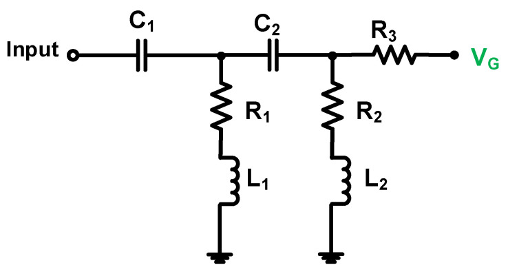
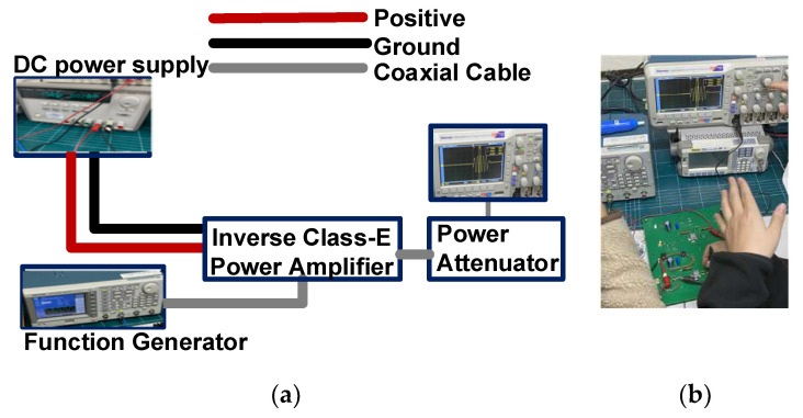
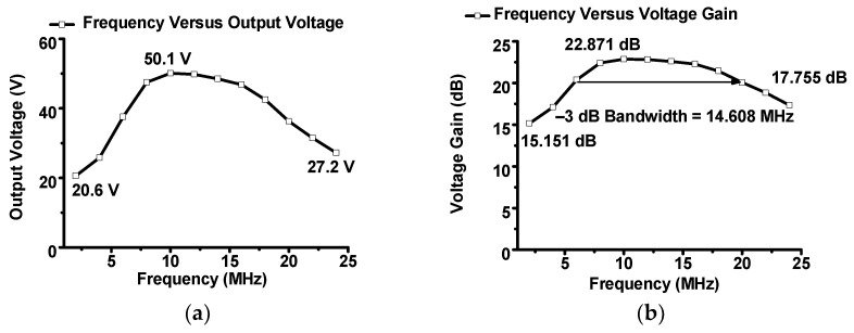
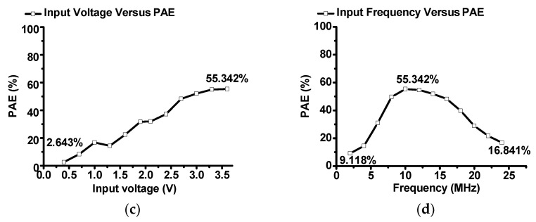
An inverse Class-E power amplifier was designed for an ultrasound transducer. The proposed inverse Class-E power amplifier can be useful because of the low series inductance values used in the output matching network that helps to reduce signal distortions. Therefore, a newly designed Class-E power amplifier can obtain a proper echo signal quality. The measured output voltage, voltage gain, voltage gain difference, and power efficiency were 50.1 V, 22.871 dB, 0.932 dB, and 55.342%, respectively. This low voltage difference and relatively high efficiency could verify the capability of the ultrasound transducer. The pulse-echo response experiment using an ultrasound transducer was performed to verify the capability of the proposed inverse Class-E power amplifier. The obtained echo signal amplitude and pulse width were 6.01 mVp-p and 0.81 μs, respectively. The -6 dB bandwidth and center frequencies of the echo signal were 27.25 and 9.82 MHz, respectively. Consequently, the designed Class-E power amplifier did not significantly alter the performance of the center frequency of the ultrasound transducer; therefore, it could be employed particularly in certain ultrasound applications that require high linearity and reasonable power efficiency.

Keywords: inverse Class-E power amplifier; ultrasound system; ultrasound transducer.


Conflict of interest statement

The authors declare no conflict of interest. The funders had no role in the study design; collection, analyses, or interpretation of data; writing of the manuscript; or the decision to publish the results.

Figures

Figure 1
Figure 1
Concept of a Class-E power amplifier for ultrasound transducer.
Figure 2
Figure 2
(a) Schematic diagram and (b) printed circuit board of the designed inverse Class-E power amplifier. (c) The magnitude and (d) phase of the impedance of the ultrasound transducer.
Figure 3
Figure 3
Schematic diagram of the input matching network.
Figure 4
Figure 4
Schematic of the output matching network.
Figure 5
Figure 5
(a) Measurement setup and (b) photo for the performance of the designed inverse Class-E power amplifier.
Figure 6
Figure 6
The experimental (a) output voltage, (b) voltage gain, (c) output voltage difference, and (d) voltage gain difference versus input voltage of the inverse Class-E power amplifier.
Figure 6
Figure 6
The experimental (a) output voltage, (b) voltage gain, (c) output voltage difference, and (d) voltage gain difference versus input voltage of the inverse Class-E power amplifier.
Figure 7
Figure 7
Measured (a) output voltage and (b) voltage gain versus input frequency, (c) PAE versus input voltage, and (d) PAE versus input frequency of the inverse Class-E power amplifier.
Figure 7
Figure 7
Measured (a) output voltage and (b) voltage gain versus input frequency, (c) PAE versus input voltage, and (d) PAE versus input frequency of the inverse Class-E power amplifier.
Figure 8
Figure 8
(a) Measurement setup and (b) photo of the pulse-echo response with designed inverse Class-E power amplifier and ultrasound transducer. The measured echo signal amplitude and spectrum in the (c) time and (d) frequency domains when using the designed inverse Class-E power amplifier and ultrasound transducer.

References

    1. Suri J.S., Kathuria C., Chang R.-F., Molinar F., Fenster A. Advances in Diagnostic and Therapeutic Ultrasound Imaging. Artech House; Norwood, MA, USA: 2008.
    1. Jung U., Choi J.H., Choo H.T., Kim G.U., Ryu J., Choi H. Fully Customized Photoacoustic System Using Doubly Q-Switched Nd: YAG Laser and Multiple Axes Stages for Laboratory Applications. Sensors. 2022;22:2621. doi: 10.3390/s22072621. - DOI - PMC - PubMed
    1. Jung U., Ryu J., Choi H. Optical Light Sources and Wavelengths within the Visible and Near-Infrared Range Using Photoacoustic Effects for Biomedical Applications. Biosensors. 2022;12:1154. doi: 10.3390/bios12121154. - DOI - PMC - PubMed
    1. Choi H., Jeong J.J., Kim J. Development of an Estimation Instrument of Acoustic Lens Properties for Medical Ultrasound Transducers. J. Healthcare Eng. 2017;2017:6580217. doi: 10.1155/2017/6580217. - DOI - PMC - PubMed
    1. Postema M. Fundamentals of Medical Ultrasound. Taylor and Francis; New York, NY, USA: 2011.

LinkOut - more resources