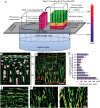
Review
. 2023 Aug;12(21):e2203205.
doi: 10.1002/adhm.202203205. Epub 2023 May 1.

Aligned Ice Templated Biomaterial Strategies for the Musculoskeletal System

Affiliations
Review

Aligned Ice Templated Biomaterial Strategies for the Musculoskeletal System

Florencia Diaz et al. Adv Healthc Mater. 2023 Aug.

Abstract

Aligned pore structures present many advantages when conceiving biomaterial strategies for treatment of musculoskeletal disorders. Aligned ice templating (AIT) is one of the many different techniques capable of producing anisotropic porous scaffolds; its high versatility allows for the formation of structures with tunable pore sizes, as well as the use of many different materials. AIT has been found to yield improved compressive properties for bone tissue engineering (BTE), as well as higher tensile strength and optimized cellular alignment and proliferation in tendon and muscle repair applications. This review evaluates the work that has been done in the last decade toward the production of aligned pore structures by AIT with an outlook on the musculoskeletal system. This work describes the fundamentals of the AIT technique and focuses on the research carried out to optimize the biomechanical properties of scaffolds by modifying the pore structure, categorizing by material type and application. Related topics including growth factor incorporation into AIT scaffolds, drug delivery applications, and studies about immune system response will be discussed.

Keywords: aligned scaffolds; biomaterials; bone tissue engineering; musculoskeletal system; unidirectional freezing.


Conflict of interest statement

The authors declare no conflicts of interest.

Figures

Figure 1
Figure 1
Mimicking of natural nacre structure via aligned ice templating (AIT). a) Scanning electron microscopy (SEM) image of sintered alumina platelet scaffold with yellow arrows highlighting the alignment. b) SEM image at higher magnification exhibits the arrangement of the alumina platelets. c) SEM image of the scaffold after compression, exhibiting the reduction in the pore size. d) SEM image of natural nacre. (a–c) Reproduced with permission.[ 14 ] Copyright 2021, Elsevier.
Figure 2
Figure 2
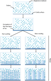
Schematic diagram showing the different stages of the ice templating process. The morphology of the ice crystals, and therefore the final pore structure, will be influenced by the process parameters, including freezing temperature, slurry composition, and more.
Figure 3
Figure 3
Factors affecting the resulting pore structure in ice templating processes. For optimizing the final material's properties, each of the parameters should be individually investigated.
Figure 4
Figure 4
The effect of freezing rate on the formation of ice crystals during ice templating in a solute/solvent system. Increasing the freezing rate results in smaller ice crystals, which in turn yields a scaffold with smaller pores after lyophilization.[ 22 ] The optimal pore size will depend on the intended application, hence the importance of selecting the appropriate freezing rate.
Figure 5
Figure 5
Reduction in pore size in an alginate ice templated scaffold with decreasing freezing temperature. Top left: −47 °C, top right: −33 °C, bottom left: −30 °C, bottom right: −25 °C. Freezing rate: 1 K mm−1. Scale bar: 200 µm. Reproduced under an open access Creative Common CC BY license.[ 33 ] Copyright 2022, the Authors. Published by Wiley‐VCH GmbH.
Figure 6
Figure 6
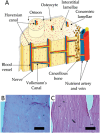
Microstructure of bone, highlighting the aligned structure of osteons and nutrient supply system to the osteocytes. A) Schematic of bone, detailing the different structures of trabecular and cortical bone. Reproduced under a Creative Commons CC‐BY license.[ 45 ] Copyright 2019, the Authors. Published by MDPI. B) Hematoxylin and eosin staining of the femoral bone of a 2–4 week‐old rat. C) Hematoxylin and eosin staining of the femoral bone of an 8–10 week‐old rat, where the alignment of the extracellular matrix is visible. Reproduced under a Creative Commons CC‐BY license.[ 46 ] Copyright 2019, the Authors. Published by MDPI.
Figure 7
Figure 7
Effect of different post‐sintering treatment on the morphology and mechanical properties of an aligned α‐ tricalcium phosphate (TCP) scaffold. a) Lamellar structure of sintered sample, untreated. b,c) Calcium‐deficient hydroxyapatite (CDHA) crystal formation after hydrothermal treatment for 3 and 8 h. d,e) CDHA crystal bundles formed after incubation at 175 °C for 12 and 72 h, respectively. f) Brushite crystal formation after immersion in acid solution. Scale bar: 15 µm. g,h) Compressive strengths of unsintered and sintered samples, respectively. * p < 0.05, ** p < 0.001). Reproduced under an open access Creative Common CC BY license.[ 66 ] Copyright 2021, the Authors. Published by Wiley‐VCH GmbH.
Figure 8
Figure 8
Investigation of oxygen plasma treatment for simvastatin (SIM) immobilization on a polycaprolactone (PCL) scaffold. a) Cumulative release of SIM from the scaffolds. b) Stress–strain curve for the different conditions. c) ALP activity of the bare and SIM loaded scaffolds. d) Expression of osteogenic biomarker of the bare and SIM loaded scaffolds. * p < 0.05, ** p < 0.005). Reproduced with permission.[ 9 ] Copyright 2021 Elsevier.
Figure 9
Figure 9
Tendon microstructure and individual units that make up the tendon extracellular matrix. Collagen type I is arranged into nanometric fibrils, which in turn are organized into fibers. These fibers are key to the mechanical properties of tendon tissue. They are arranged into fascicles, which are surrounded by a fascicular membrane containing a diverse cell population. Reproduced with permission.[ 108 ] Copyright 2017, Elsevier.
Figure 10
Figure 10
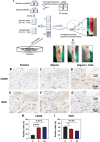
Silk fibroin aligned scaffold tested on an in vivo tendon rat model. a) Schematic representation of the experimental steps. b–d) Immunohistochemical staining with C206 antibody (anti‐inflammatory marker) for all three experimental conditions. e–g) Immunohistochemical staining with iNOS antibody (pro‐inflammatory marker) for all three experimental conditions. h) Percentage of C206 positive cells. i) Percentage of iNOS positive cells. * p < 0.05, **** p < 0.0001. Reproduced under an open access Creative Common CC BY license.[ 117 ] Copyright 2021, the Authors. Published by BioMed Central.
Figure 11
Figure 11
Schematic of the microstructure of skeletal muscle, where myofibers represent the structural units of the fascicles that make up the bulk of the tissue. Scaffolds designed for this application should support and promote the formation of myotubes in vitro and in vivo. Reproduced under an open access Creative Common CC BY license.[ 129 ] Copyright 2020, the Authors. Published by MDPI.
Figure 12
Figure 12
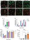
Collagen‐glycosaminoglycan (GAG) scaffold doped with electroconductive polymers for muscle tissue engineering. a–h) Fluorescence staining in both transversal and longitudinal directions for PEDOT containing scaffolds frozen at different temperatures. i) Conductivity of the collagen, poly(3,4‐ethylenedioxythiophene (PEDOT), and polypyrrole (PPy) loaded scaffolds. j) Metabolic activity of the collagen, PEDOT, and PPy scaffolds after 1, 4, and 7 days in culture. k) Metabolic activity of the PEDOT loaded scaffolds frozen at different temperatures. l) MyoD expression of the different PEDOT scaffolds. * p < 0.05, ** p < 0.01, *** p < 0.001. Reproduced under an open access Creative Common CC BY license.[ 130 ] Copyright 2022, the Authors. Published by Wiley‐VCH GmbH.
Figure 13
Figure 13
Cartilage microstructure, highlighting the three distinct zones and their morphology. A) Schematic representation of cartilage microstructure. The transitional zone has no preferred alignment, contrasting with the deep zone where the collagen fibers align vertically. B) Scanning electron microscopy (SEM) image of the superficial zone of pig articular cartilage, exhibiting horizontal alignment. C) SEM image of the transition zone of pig articular cartilage. No preferential orientation is evident. D) SEM image of the deep zone of pig articular cartilage, exhibiting vertical orientation. Scale bars: 2 µm. (A) Reproduced under an open access Creative Common CC BY license.[ 140 ] Copyright 2020, the Authors. Published by Frontiers. (B–D) Reproduced under an open access Creative Common CC BY license.[ 141 ] Copyright 2014, the Authors. Published by BioMed Central.
Figure 14
Figure 14
Chitosan–gelatin bilayer scaffold produced with sequential freezing. a) Schematic representation of the bidirectional freezing method. b) Schematic representation of the collagen fiber alignment and cell infiltration. SZ: Superficial zone; TZ: Transition zone; DZ: Deep Zone. c) Fluorescence staining image of the seeded scaffold. d) Cell densities in the different zones of the scaffold. e–g) Fluorescence staining images of the SZ, TZ, and DZ, respectively. Reproduced with permission.[ 26 ] Copyright 2015 Elsevier Ltd.

Similar articles

References

    1. Shao G., Hanaor D. A. H., Shen X., Gurlo A., Adv. Mater. 2020, 32, 1907176. - PubMed
    1. Deville S., Meille S., Seuba J., Sci. Technol. Adv. Mater. 2015, 16, 043501. - PMC - PubMed
    1. Gaudillere C., Serra J. M., Bol. Soc. Esp. Cerám. Vidrio 2016, 55, 45.
    1. Gaudillere C., Garcia‐Fayos J., Serra J. M., J. Mater. Chem. 2014, 2, 3828.
    1. a) Sahoo P. K., Aepuru R., Panda H. S., Bahadur D., Sci. Rep. 2015, 5, 17726; - PMC - PubMed
    2. b) Deng P., Jiao Q., Ren H., J. Mater. Sci. 2021, 56, 2077.

Publication types

LinkOut - more resources