. 2023 Apr 15;25(4):1208-1236.
doi: 10.1093/europace/euad043.

EHRA clinical consensus statement on conduction system pacing implantation: endorsed by the Asia Pacific Heart Rhythm Society (APHRS), Canadian Heart Rhythm Society (CHRS), and Latin American Heart Rhythm Society (LAHRS)

Affiliations

EHRA clinical consensus statement on conduction system pacing implantation: endorsed by the Asia Pacific Heart Rhythm Society (APHRS), Canadian Heart Rhythm Society (CHRS), and Latin American Heart Rhythm Society (LAHRS)

Haran Burri et al. Europace. .

Abstract

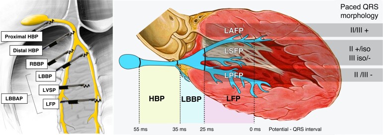
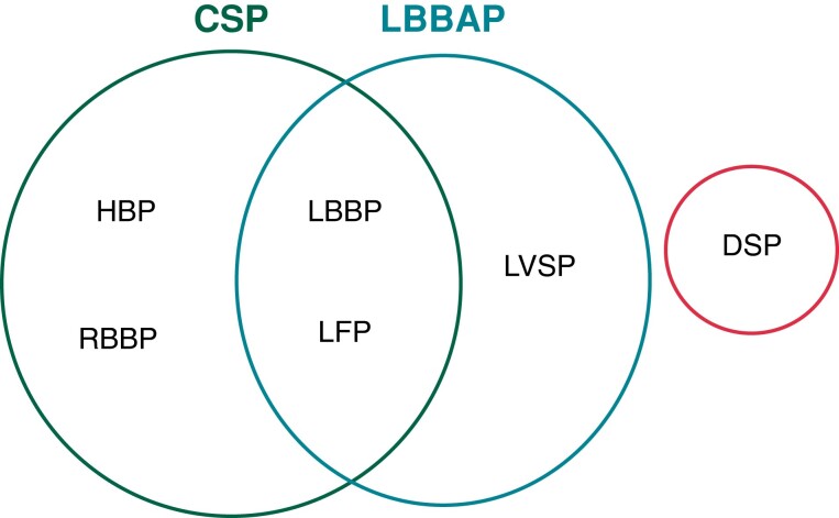
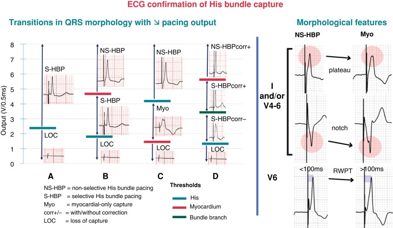
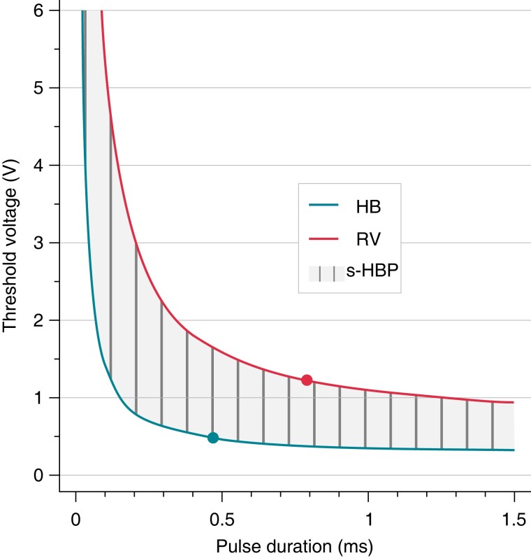
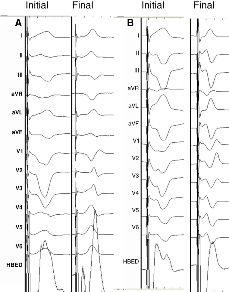
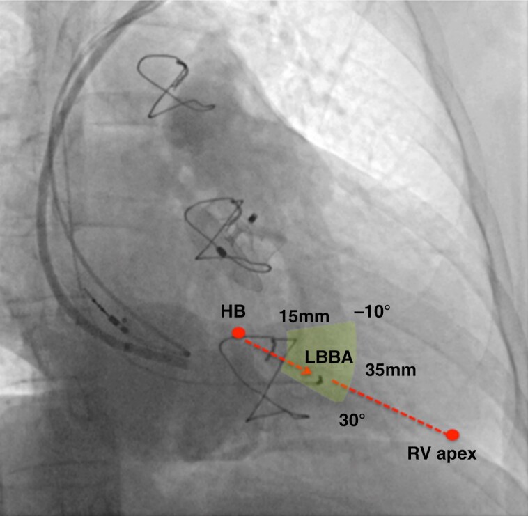
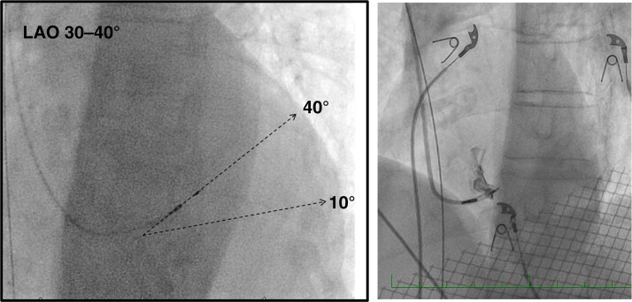
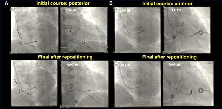
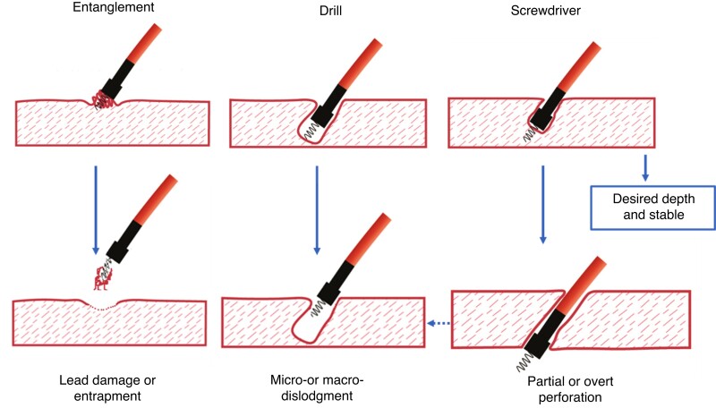
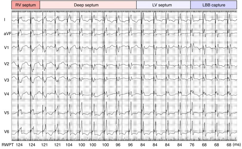
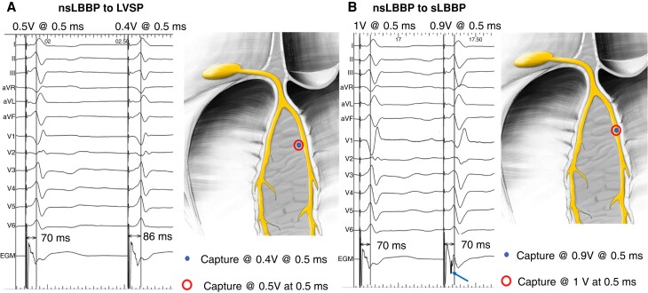
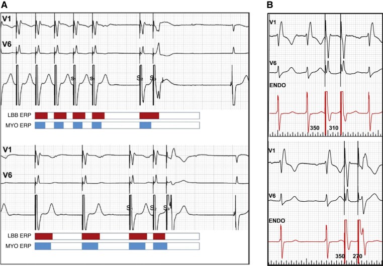
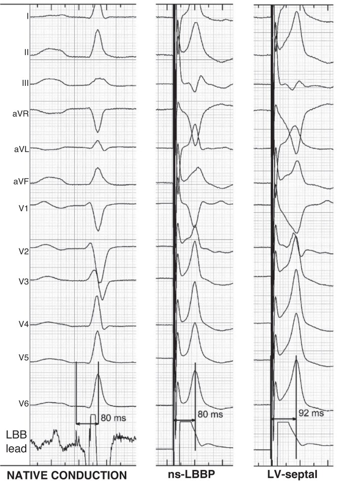
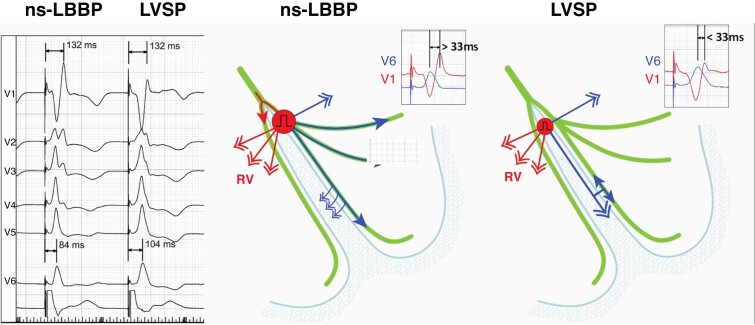
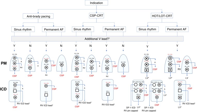
Conduction system pacing (CSP) has emerged as a more physiological alternative to right ventricular pacing and is also being used in selected cases for cardiac resynchronization therapy. His bundle pacing was first introduced over two decades ago and its use has risen over the last five years with the advent of tools which have facilitated implantation. Left bundle branch area pacing is more recent but its adoption is growing fast due to a wider target area and excellent electrical parameters. Nevertheless, as with any intervention, proper technique is a prerequisite for safe and effective delivery of therapy. This document aims to standardize the procedure and to provide a framework for physicians who wish to start CSP implantation, or who wish to improve their technique.

Keywords: Conduction system pacing; Device implantation; His bundle pacing; Left bundle branch area pacing.


Figures

Figure 1
Figure 1
Categories of conduction system pacing. Anatomical position of the pacing lead, potential to QRS interval (if visualized), and paced QRS morphology in leads II and III are used to determine the level of CSP. RBBP and LVSP are not shown on the right panel. HBP = His bundle pacing; iso = isoelectric; LAFP = left anterior fascicle pacing; LBBAP = left bundle branch area pacing; LBBP = left bundle branch pacing; LFP = left fascicular pacing; LPFP = left posterior fascicle pacing; LSFP = left septal fascicle pacing; LVSP = left ventricular septal pacing; RBBP = right bundle branch pacing. Modified with permission from Filip Plesinger and from Jastrzebski et al.
Figure 2
Figure 2
Synopsis of different entities of CSP and related forms of stimulation.CSP = conduction system pacing; DSP = deep septal pacing; HBP = His bundle pacing; LBBAP = left bundle branch area pacing; LBPP = left bundle branch pacing; LFP = left fascicular pacing; LVSP = left ventricular septal pacing; RBBP = right bundle branch pacing.
Figure 3
Figure 3
Proximal RBBP with double QRS transition during threshold test. V6 R-wave peak times (V6RWPT) in milliseconds are indicated by the numbers and transitions are shown by the arrows at the bottom of the figure. Non-selective His bundle pacing (ns-HBP) transitions to non-selective right bundle branch pacing (ns-RBBP). Prolongation of V6RWPT by 11 ms (there is also a slight change in overall QRS morphology—see lead V2—illustrating the importance of recording a 12-lead ECG during threshold testing of CSP). Second transition is from ns-RBBP to selective (s-) RBBP. Note the change in the QRS axis with loss of myocardial capture. Pseudo-shortening of V6RWPT by 2 ms is related to change of R morphology to rS morphology in V6. The RBB potential to QRS interval of 30 ms recorded at the pacing lead implantation site is much shorter than latency interval during s-RBBP with a stimulus to QRS interval of 66 ms (not shown). Likewise, the potential to V6RWPT of 68 ms (not shown) is significantly shorter than the V6RWPT of 92 ms during s-RBBP. Moreover, s-RBBP QRS morphology is different from native QRS (most readily visible in V1–V3).
Figure 4
Figure 4
ECGs illustrating LBBP, LFP, and LVSP. QRS axis results both from conduction system capture and surrounding myocardial capture. Note the similarity in morphology between LBBP and left LAFP, which may be distinguished by the potential to QRS interval (if present) and anatomic lead position. The potential to QRS intervals recorded in the intrinsic rhythm by the pacing lead is also shown for LBBP and LFP. Sweep speed of 25 mm/s for the paced QRS tracings and 100 mm/s for those in intrinsic rhythm. Abbreviations as for Figure 1. Modified with permission from Jastrzebski et al.
Figure 5
Figure 5
(A) Connection setup for CSP (modified, with permission, from Medtronic). (B) Screen setup with the 12-lead ECG and intracardiac electrogram recorded at 100 mm/s sweep speed during LBBAP implantation, with a filtered 30–500 Hz channel (cyan) and unfiltered 0.5–500 Hz channel (green). V1 and V6 are coloured in yellow to be distinguished from the other leads to facilitate analysis in real time. Note the COI in the unfiltered channel, and transition from non-selective to selective LBBP (last two cycles) with changes in ECG and EGM morphology. CSP F = conduction system pacing, filtered; CSP NF = conduction system pacing, non-filtered.
Figure 6
Figure 6
Examples of sinus rhythm with nodal (top panel) and infra-nodal block (middle and bottom panels). His potentials are only visible with infra-nodal block during blocked cycles. Pacing spikes (*) from a temporary lead may mimic His potentials. The two bottom tracings were recorded using a Merlin programmer (Abbott, Sylmar, CA, USA) with filtered (middle panel) and unfiltered (bottom panel) signals at a 0.05 mV/mm gain setting. A = atrial; AVB = atrioventricular block; H = His; V = ventricular.
Figure 7
Figure 7
Mapping the distal His bundle in a patient with infra-nodal block. Top panel: intracardiac electrograms from the HBP lead demonstrate a larger atrial electrogram (A) and prominent His (H) potential, where distal His capture could be achieved only at a high output due to HV block (despite COI of the His potential shown by the arrow). Ventricular pacing is delivered by an additional back-up lead. Bottom panel: at a slightly distal location, much smaller atrial electrogram is noted with His potential (likely far-field) where distal His capture is achieved at low output (1 V). Fluoroscopic images of the proximal and distal His positions of the HBP lead are shown along with schematic representation of the site of conduction block. Adapted with permission from Vijayaraman et al.
Figure 8
Figure 8
Contrast injection via a delivery sheath in a RAO view to delineate the tricuspid annulus. The atrioventricular node (AVN) and His bundle are depicted in yellow, and the coronary sinus ostium (CS os) is depicted by the dotted circle. The patient had prior mitral annuloplasty and VVI pacemaker implantation and underwent upgrade due to pacing-induced cardiomyopathy.
Figure 9
Figure 9
His bundle COI as a marker guiding successful lead deployment. Despite apparently proper lead fixation with ≥5 lead rotations and acceptable acute threshold (left panel), the lead was not well deployed. After additional rotations, torque build-up was felt and a current of injury (blue arrow) and negative His potential (red arrow) were visible with a significant improvement of capture threshold (right panel). The lead was initially not in good contact with the His bundle and potentially unstable, thus increasing the risk of late threshold rise. Unipolar electrogram from pacing lead: uni_f—filters: 30–500 Hz; uni_uf—filters: 0.5–500 Hz.
Figure 10
Figure 10
ECG features to diagnose His bundle capture. Left panel: a number of different transitions in QRS morphology may be observed with decrementing pacing output, reflecting loss of His capture, myocardial capture, or correction of bundle branch block. The sequence of transition will depend upon the respective thresholds. (A) Obligatory S-HBP. (B) Transition from NS-HBP to S-HBP. (C) Transition from NS-HBP to myocardial capture only. (D) Transition from NS-HBP to S-HBP with and without correction of bundle branch block. Right panel: morphological features combining the absence of plateaus, notching, and/or slurring in leads I, V1, and V4 to V6 and V6 R-wave peak time (RWPT) < 100 ms indicate NS-HBP and allow to distinguish this entity from simple myocardial capture. Adapted with permission from Burri et al.
Figure 11
Figure 11
Pacing chronaxie (dots) for His bundle (HB) is shorter than for right ventricular (RV) myocardium. Consequently, zone of selective pacing (s-HBP) widens with shortening of the pulse duration. By the same token, longer pulse duration facilitates simultaneous capture of both His bundle and RV myocardium. Adapted, with permission, from Jastrzebski et al.
Figure 12
Figure 12
Localizing the initial lead deployment site on the septum with initial pacemapping of the right septum and final position after screwing the lead up to the left septal sub-endocardium. In panel (A), there is the recommended QRS polarity in leads II (slightly positive) and III (negative) while panel (B) illustrates the alternative, more inferior implantation site with negative QRS in both II and III. The nadir notch in V1 (‘W’ morphology) is observed in both cases. Notably, initial paced QRS morphologies anticipated the final portion of the left-sided conduction tissue that was engaged: in case (A), proximal LBB or LSF; in case (B), LPF.
Figure 13
Figure 13
Insertion site for left bundle area pacing. In a RAO view at 30° with pacing lead in the left bundle area (LBBA) region, contrast is injected through a sheath delineating right atrial and ventricular anatomy. Tricuspid valve leaflets are identified by contrast. The summit of the tricuspid annulus indicates the approximate His bundle (HB) position. The red arrow indicates an imaginary line that connects the tricuspid annulus summit/His bundle with the RV apex, which can serve as a guide for placing the left bundle area lead. Successful pacing sites can be localized within a sector (indicated in yellow) located 15–35 mm away from the tricuspid annulus summit and at an angle of −10° to 30°, as described by Liu et al.
Figure 14
Figure 14
Left panel: LAO view for orienting the lead 10–40° (most often 20–30°) with respect to the horizontal plane for perpendicular septal penetration. Right panel: example of lead orientation assisted by septography in the LAO view.
Figure 15
Figure 15
Importance of the RAO view for evaluating issues with lead orientation which may appear adequate in the LAO view (top panels) and after re-positioning (bottom panels) in two patients. (A) Patient without clear progression of the lead in LAO view, with basal orientation of the lead revealed by the RAO view. (B) Another patient with apparent lead progression in the LAO view but without terminal R in V1 and no change in V6RWPT, with antero-apical orientation of the lead revealed by the RAO view.
Figure 16
Figure 16
Lead behaviour during penetration of the septum during LBBAP. Both drill and screwdriver effects can result in perforation.
Figure 17
Figure 17
Pacemapping for lead depth in the septum. Continuous pacing during intra-septal lead deployment enables to monitor continuous change of paced QRS complex morphology and lead depth in the septum. The right ventricular (RV septum) paced QRS is characterized by notches in lateral leads, ‘W’ morphology in V1, and time to R-wave peak (RWPT) in V6 > 120 ms. Deep septal paced QRS is narrower and loses notches in lateral leads, the notch in V1 moves towards the end of QRS, and V6RWPT is usually in the range of 120–95 ms. Pacing close to the left bundle branch area (LV septum) QRS is characterized by a positive terminal component in lead V1, pseudo-delta in leads V5–V6, and V6RWPT of 95–80 ms. LBB capture paced QRS is characterized by deeper S-wave in leads I, V5–V6, more prominent R in V1–V3, and V6RWPT usually <80 ms. LBB capture in the current case was assured both by V6RWPT < 74 ms and transition to selective capture (not shown).
Figure 18
Figure 18
Fixation (or ‘template’) beats of different morphologies, reflecting depth of lead penetration. Reproduced with permission from Jastrzebski et al.
Figure 19
Figure 19
Myocardial COI during lead progression. A 15 s strip of the endocardial signals from the lead tip recorded during LBBAP implantation with continuous pacing at 100 bpm. Immediately after the premature fixation beat, preceded by a Purkinje potential (arrow), there is an obvious drop of the paced myocardial COI. Both COI drop and Purkinje potential are valuable markers indicating that the subendocardial area of the interventricular septum was reached by the pacing lead tip and that the lead rotations should be immediately stopped. In the present case, the lead rotations were continued and a further decrease in COI was observed (<4 mV and <25% of V wave), indicating imminent perforation. The endocardial signals (ENDO) from the pacing lead are acquired in unipolar mode and presented as filtered (30–100 Hz) and unfiltered (0.1–500 Hz). Sweep speed 12.5 mm/s. Reproduced, with permission from Jastrzebski et al.
Figure 20
Figure 20
Left bundle branch pacing lead implantation in a patient with LBBB, with electrograms during an intrinsic-conducted rhythm. A fascicular potential (arrows) is visualized within the ventricular electrogram during LBBB (first and last cycles) and is pre-systolic when the QRS narrows following a pause (after an atrial premature beat, not visible here). Modified, with permission, from Kaddour et al.
Figure 21
Figure 21
(A) Contrast injection via delivery sheath to delineate the endocardial surface and depth of penetration of the intra-septal lead. (B) Pacing from the ring electrode also provides information regarding depth of penetration.
Figure 22
Figure 22
(A) Transition between ns-LBBP and myocardial capture only with LVSP at 0.5 V@0.5 ms. This type of transition is characterized by prolongation of the V6RWPT, terminal R, or r amplitude decrease in V1 and usually by the disappearance of the S-wave in I/V6 during myocardial capture, but without a significant change in the local ventricular EGM signal. (B) A transition between ns-LBBP and s-LBBP at 1 V@0.5 ms is shown. This type of transition is characterized by prolongation of the QRS (measured from the pacing artefact). Usually, there is a change in QRS morphology from QR/qR to rSR in V1 (with rounding of the R’) and the development of a deeper S in I/V6 during s-LBBP, without change in V6RWPT. In the ventricular EGM signal, discrete local ventricular potential appears during s-LBBP (blue arrow)—indicating that local myocardium was no longer captured. Modified, with permission by Filip Plesinger.
Figure 23
Figure 23
Programmed left bundle branch (LBB) area stimulation. (A) ‘Myocardial’ and selective LBB responses in the same patient. Top panel: fast drive shortens the refractoriness of septal myocardium; then, long pause (S2) prolongs refractoriness of the LBB; consequently, S3 finds myocardium excitable but LBB refractory (myocardial response). Bottom panel: slow drive prolongs refractoriness of the myocardium; then, short-coupled S2 shortens the refractoriness of the LBB; consequently, S3 finds myocardium refractory but LBB excitable (selective response). Reproduced with permission from Jastrzebski. (B) Double extra-stimuli delivered during intrinsic rhythm. Top panel: no change in QRS morphology with S2 coupling interval of 320 ms. Bottom panel: with S2 of 270 ms, a selective response is observed (note: also splitting of the signal in the endocardial channel).
Figure 24
Figure 24
Native and paced activation times of the left ventricle are equal when the conduction system is captured. LBB potential to V6RWPT is 80 ms, the same as stimulus to V6RWPT during ns-LBBP. In contrast, during loss of LBB capture, stimulus to V6RWPT is >10 ms longer than during intrinsic activation or ns-LBBP.
Figure 25
Figure 25
Illustration of effect of ns-LBBP and loss of conduction tissue capture resulting in LVSP with myocardial capture only, on V6–V1 inter-peak interval, occurring during a threshold test. R-wave peak time in V1 reflects right ventricular activation that depends on transseptal conduction and is not affected by conduction tissue capture. RWPT in V6 reflects activation of the lateral wall of the left ventricle and is not influenced by loss of septal myocardial capture. Consequently, a longer V6–V1 interval is observed with left conduction system capture. Modified, with permission, from Jastrzebski et al.
Figure 26
Figure 26
Sudden prolongation of V6RWPT when reducing pacing output during LBBAP implantation, indicating loss of conduction system capture. An additional lead rotation resulted in conduction system capture threshold of 0.6V@0.5 ms. Note that other changes in QRS morphology are very subtle, and there is absence of a terminal r or R-wave in V1 despite the presence of conduction system capture.
Figure 27
Figure 27
Algorithm for confirming conduction system capture with LBBAP. Some of the steps may be skipped according to operator preference, experience, or feasibility to perform particular measurements/manoeuvres. DSP = deep septal pacing; IVCD = intra-ventricular conduction delay; LBBAP = left bundle branch area pacing; LBBB = left bundle branch block; ns-LBBP = non-selective left bundle branch pacing; RBBB = right bundle branch block; RBBP = right bundle branch pacing; RWPT = R-wave peak time; s-LBBP = selective left bundle branch pacing.
Figure 28
Figure 28
Current of injury morphology from the LBBAP lead in a patient with the lead in the left ventricular (LV) subendocardial region and in another patient with septal perforation. In contrast to adequate lead position, with perforation, the COI amplitude from the tip electrode is low and less than from the ring electrode, with a QR morphology indicating overt perforation (although unipolar capture was still possible here at 1.7 V/0.5 ms, with a pacing impedance of 380 Ω).
Figure 29
Figure 29
Micro-perforation of a 3830 lead in the LBB position with intact electrical parameters. No re-positioning was attempted, and there were no clinical sequelae.
Figure 30
Figure 30
Device configuration for CSP according to device indication, underlying rhythm (i.e. requirement for an atrial lead), presence on an additional ventricular lead. In all cases with a CSP lead plugged to the RV port, adequate sensing must be ensured. Not shown here are additional configurations with Y adapters and HOT-CRT with a His lead in combination with an RV lead only (which may be used in case of uncorrected selective His capture with isolated right bundle branch block). 1Additional ventricular lead may be indicated for ICD therapy, back-up pacing, adequate ventricular sensing, or CRT optimization. 2The LV lead is plugged to the RV port in case the CSP lead does not provide proper sensing (atrial or His potential oversensing and ventricular undersensing are issues that may be encountered with HBP). *DF-1 ICD lead may also be used; #IS-1 LV lead may also be used. A = atrial; AF = atrial fibrillation; CRT = cardiac resynchronization therapy; CSP = conduction system pacing; HOT/LOT-CRT = His-optimized or left bundle pacing-optimized CRT; ICD = implantable cardioverter defibrillator; LV = left ventricle; PM = pacemaker; RA = right atrial; RV = right ventricle.

References

    1. Brugada J, Katritsis DG, Arbelo E, Arribas F, Bax JJ, Blomstrom-Lundqvist Cet al. . 2019 ESC Guidelines for the management of patients with supraventricular tachycardia. The task force for the management of patients with supraventricular tachycardia of the European Society of Cardiology (ESC). Eur Heart J 2020;41:655–720. - PubMed
    1. Glikson M, Nielsen JC, Kronborg MB, Michowitz Y, Auricchio A, Barbash IMet al. . 2021 ESC Guidelines on cardiac pacing and cardiac resynchronization therapy. Europace 2022;24:71–164. - PubMed
    1. Burri H, Starck C. EHRA expert consensus statement and practical guide on optimal implantation technique for conventional pacemakers and implantable cardioverter-defibrillators: endorsed by the Heart Rhythm Society (HRS), the Asia Pacific Heart Rhythm Society (APHRS), and the Latin-American Heart Rhythm Society (LAHRS)-a role for postoperative ultrasound? Authors’ reply. Europace 2021;24:523–24. - PubMed
    1. Bakelants E, Burri H. Troubleshooting programming of conduction system pacing. Arrhythm Electrophysiol Rev 2021;10:85–90. - PMC - PubMed
    1. Burri H, Keene D, Whinnett Z, Zanon F, Vijayaraman P. Device programming for His bundle pacing. Circ Arrhythm Electrophysiol 2019;12:e006816. - PMC - PubMed

Publication types