

Mechanical alignment tolerance of a cruciate-retaining knee prosthesis under gait loading-A finite element analysis
- PMID: 37064225
- PMCID: PMC10098169
- DOI: 10.3389/fbioe.2023.1148914
Mechanical alignment tolerance of a cruciate-retaining knee prosthesis under gait loading-A finite element analysis
Abstract
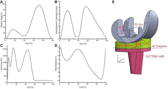
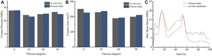
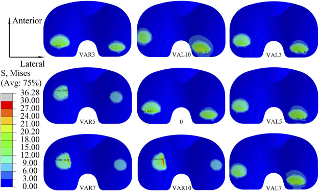
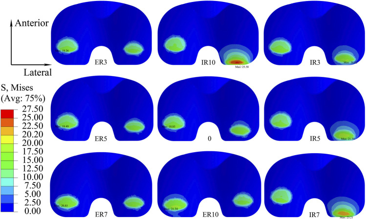
Component alignment is one of the most crucial factors affecting total knee arthroplasty's clinical outcome and survival. This study aimed to investigate how coronal, sagittal, and transverse malalignment affects the mechanical behavior of the tibial insert and to determine a suitable alignment tolerance on the coronal, sagittal, and transverse planes. A finite element model of a cruciate-retaining knee prosthesis was assembled with different joint alignments (-10°, -7°, -5°, -3°, 0°, 3°, 5°, 7°, 10°) to assess the effect of malalignment under gait loading. The results showed that varus or valgus, extension, internal rotation, and excessive external rotation malalignments increased the maximum Von Mises stress and contact pressure on the tibial insert. The mechanical alignment tolerance of the studied prosthesis on the coronal, sagittal, and transverse planes was 3° varus to 3° valgus, 0°-10° flexion, and 0°-5° external rotation, respectively. This study suggests that each prosthesis should include a tolerance range for the joint alignment angle on the three planes, which may be used during surgical planning.
Keywords: alignment tolerance; contact pressure; finite element analysis; gait loading; knee prosthesis; stress.
Copyright © 2023 Luan, Wang, Fang, Zhang, Li, Zhang, Liu, Su and Cheng.
Conflict of interest statement
The authors declare that the research was conducted in the absence of any commercial or financial relationships that could be construed as a potential conflict of interest.
Figures


Similar articles
-
Comprehensive Impact of Multiplanar Malalignment on Prosthetic Mechanics Under Gait Loading After Total Knee Arthroplasty-A Finite Element Analysis.Orthop Surg. 2025 Jul;17(7):2112-2120. doi: 10.1111/os.70068. Epub 2025 May 27. Orthop Surg. 2025. PMID: 40425489 Free PMC article.
-
Preservation of femoral and tibial coronal alignment to improve biomechanical effects of medial unicompartment knee arthroplasty: Computational study.Biomed Mater Eng. 2018;29(5):651-664. doi: 10.3233/BME-181015. Biomed Mater Eng. 2018. PMID: 30400078
-
Does Coronal Plane Malalignment of the Tibial Insert in Total Ankle Arthroplasty Alter Distal Foot Bone Mechanics? A Cadaveric Gait Study.Clin Orthop Relat Res. 2020 Jul;478(7):1683-1695. doi: 10.1097/CORR.0000000000001294. Clin Orthop Relat Res. 2020. PMID: 32574472 Free PMC article.
-
The effect of malalignment on stresses in polyethylene component of total knee prostheses--a finite element analysis.Clin Biomech (Bristol). 2002 Feb;17(2):140-6. doi: 10.1016/s0268-0033(01)00109-7. Clin Biomech (Bristol). 2002. PMID: 11832264
-
[Research progress on finite element analysis of unicompartmental knee arthroplasty in medial knee compartmental osteoarthritis].Zhongguo Xiu Fu Chong Jian Wai Ke Za Zhi. 2021 Jun 15;35(6):781-785. doi: 10.7507/1002-1892.202101028. Zhongguo Xiu Fu Chong Jian Wai Ke Za Zhi. 2021. PMID: 34142508 Free PMC article. Review. Chinese.
Cited by
-
Impact of knee geometry on joint contact mechanics after meniscectomy.Sci Rep. 2024 Nov 19;14(1):28595. doi: 10.1038/s41598-024-79662-y. Sci Rep. 2024. PMID: 39562771 Free PMC article.
-
Investigation into the effect of deltoid ligament injury on rotational ankle instability using a three-dimensional ankle finite element model.Front Bioeng Biotechnol. 2024 May 1;12:1386401. doi: 10.3389/fbioe.2024.1386401. eCollection 2024. Front Bioeng Biotechnol. 2024. PMID: 38751867 Free PMC article.
-
Comprehensive Impact of Multiplanar Malalignment on Prosthetic Mechanics Under Gait Loading After Total Knee Arthroplasty-A Finite Element Analysis.Orthop Surg. 2025 Jul;17(7):2112-2120. doi: 10.1111/os.70068. Epub 2025 May 27. Orthop Surg. 2025. PMID: 40425489 Free PMC article.
References
-
- Abdel M. P., Ollivier M., Parratte S., Trousdale R. T., Berry D. J., Pagnano M. W. (2018). Effect of postoperative mechanical Axis alignment on survival and functional outcomes of modern total knee arthroplasties with cement: A concise follow-up at 20 years. J. bone Jt. Surg. Am. volume 100 (6), 472–478. 10.2106/jbjs.16.01587 - DOI - PubMed
-
- ASTM. F3141-17a (2017). Standard guide for total knee replacement loading Profiles2017. Available from: https://www.astm.org/f3141-17a.html .
-
- Bauer L., Kistler M., Steinbrück A., Ingr K., Müller P. E., Jansson V., et al. (2021). Different ISO standards’ wear kinematic profiles change the TKA inlay load. Appl. Sci. 11 (7), 3161. 10.3390/app11073161 - DOI
LinkOut - more resources
Full Text Sources