

Fouling in reverse osmosis membranes: monitoring, characterization, mitigation strategies and future directions
- PMID: 37064488
- PMCID: PMC10102236
- DOI: 10.1016/j.heliyon.2023.e14908
Fouling in reverse osmosis membranes: monitoring, characterization, mitigation strategies and future directions
Abstract
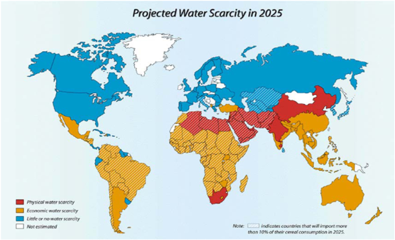
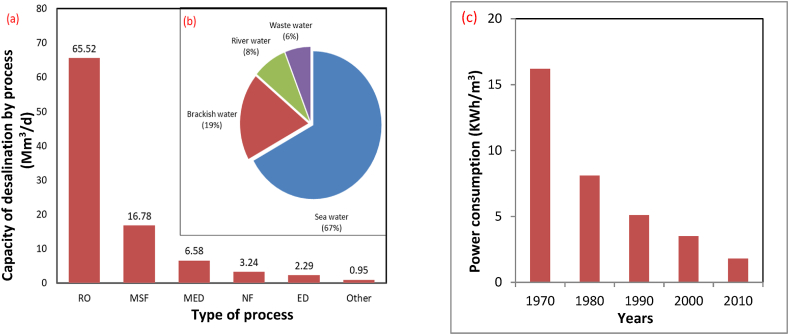
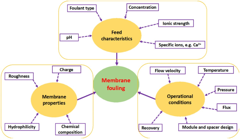
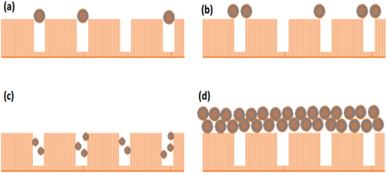
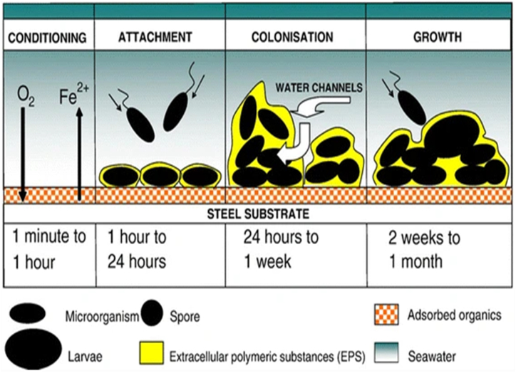
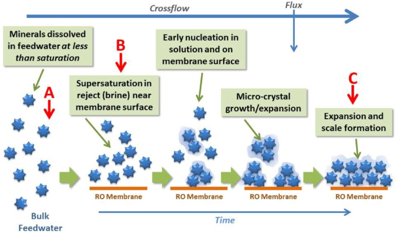
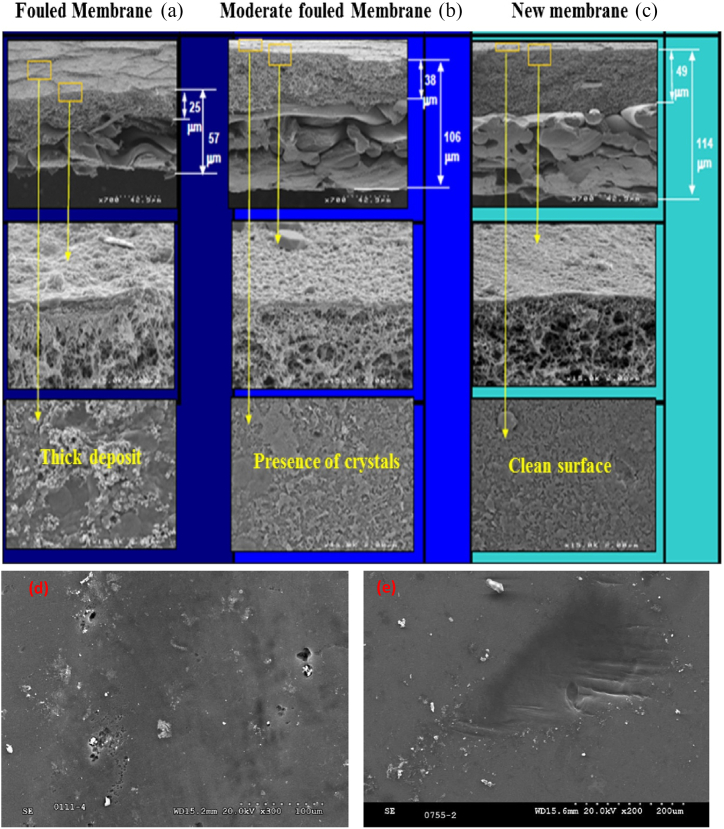
Water scarcity has been a global challenge for many countries over the past decades, and as a result, reverse osmosis (RO) has emerged as a promising and cost-effective tool for water desalination and wastewater remediation. Currently, RO accounts for >65% of the worldwide desalination capacity; however, membrane fouling is a major issue in RO processes. Fouling reduces the membrane's lifespan and permeability, while also increases the operating pressure and chemical cleaning frequency. Overall, fouling reduces the quality and quantity of desalinated water, and thus hinders the sustainable application of RO membranes by disturbing its efficacy and economic aspects. Fouling arises from various physicochemical interactions between water pollutants and membrane materials leading to foulants' accumulation onto the membrane surfaces and/or inside the membrane pores. The current review illustrates the main types of particulates, organic, inorganic and biological foulants, along with the major factors affecting its formation and development. Moreover, the currently used monitoring methods, characterization techniques and the potential mitigation strategies of membrane fouling are reviewed. Further, the still-faced challenges and the future research on RO membrane fouling are addressed.
Keywords: Characterization of foulants; Fouling monitoring and mitigation; Membrane modification; RO-Membranes.
© 2023 The Author(s).
Figures
References
-
- Ramachandra T., Solanki M. Ecological assessment of lentic water bodies of Bangalore. The Ministry of Science and Technology. 2007;25:96.
-
- Adel M., et al. Removal of heavy metals and dyes from wastewater using graphene oxide-based nanomaterials: a critical review. Environ. Nanotechnol., Monit. Manage. 2022;18:100719.
-
- Rosegrant M.W., Cai X., Cline S.A. International Food Policy Research Institute; Washington, U.S.A: 2002. Global water outlook to 2025-averting an impending crisis: a 2020 vision for food, agriculture, and the environment initiative. ISBN: 0-89629-646-6.
-
- Matin A., et al. Fouling control in reverse osmosis for water desalination & reuse: current practices & emerging environment-friendly technologies. Sci. Total Environ. 2021;765:142721. - PubMed
Publication types
LinkOut - more resources
Full Text Sources
Research Materials
Miscellaneous
