. 2023 May 16;122(10):1868-1882.
doi: 10.1016/j.bpj.2023.04.018. Epub 2023 Apr 18.

High curvature promotes fusion of lipid membranes: Predictions from continuum elastic theory

Affiliations

High curvature promotes fusion of lipid membranes: Predictions from continuum elastic theory

Gonen Golani et al. Biophys J. .

Abstract

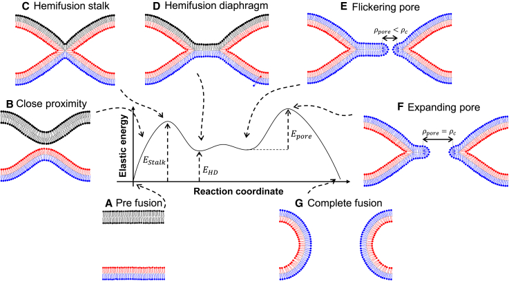
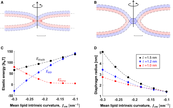
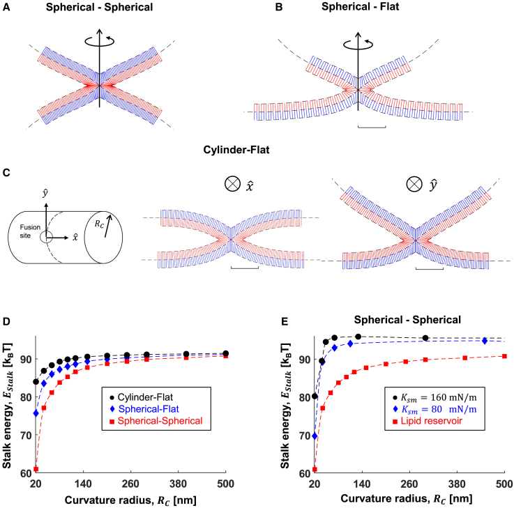
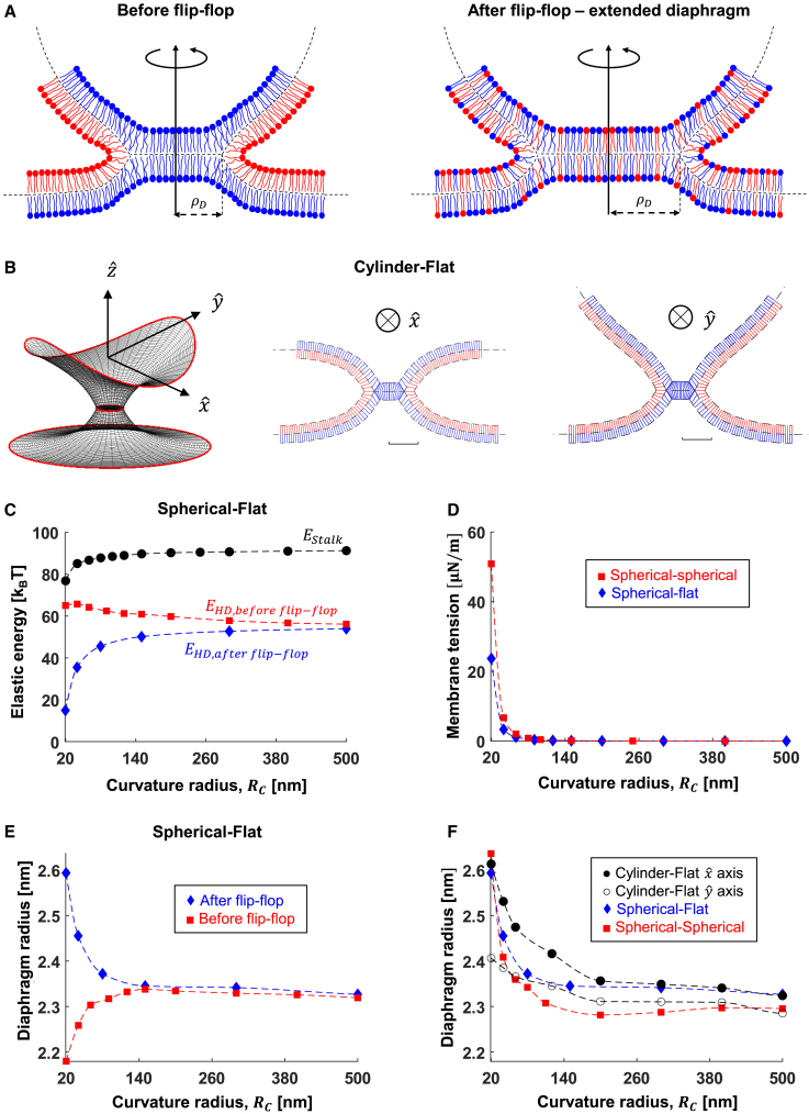
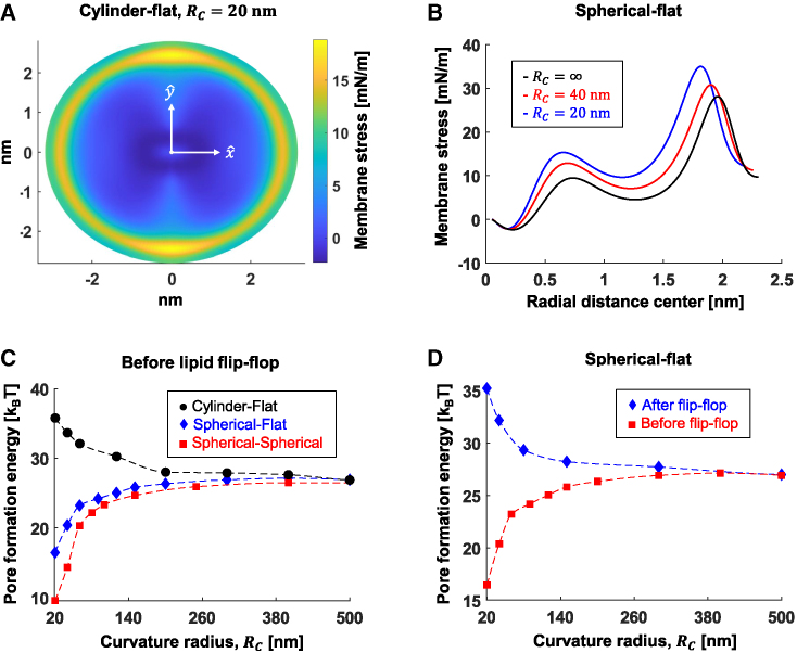
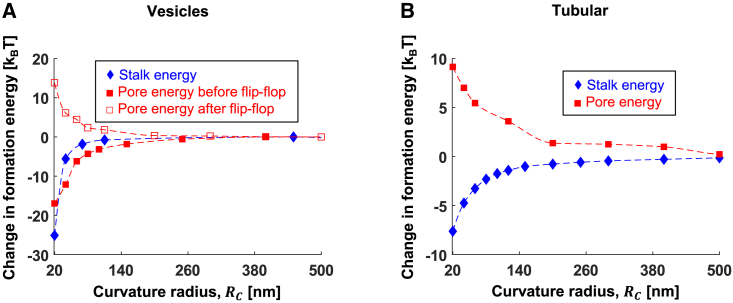
The fusion of lipid membranes progresses through a series of hemifusion intermediates with two significant energy barriers related to the formation of stalk and fusion pore, respectively. These energy barriers determine the speed and success rate of many critical biological processes, including the fusion of highly curved membranes, for example synaptic vesicles and enveloped viruses. Here we use continuum elastic theory of lipid monolayers to determine the relationship between membrane shape and energy barriers to fusion. We find that the stalk formation energy decreases with curvature by up to 31 kBT in a 20-nm-radius vesicle compared with planar membranes and by up to 8 kBT in the fusion of highly curved, long, tubular membranes. In contrast, the fusion pore formation energy barrier shows a more complicated behavior. Immediately after stalk expansion to the hemifusion diaphragm, the fusion pore formation energy barrier is low (15-25 kBT) due to lipid stretching in the distal monolayers and increased tension in highly curved vesicles. Therefore, the opening of the fusion pore is faster. However, these stresses relax over time due to lipid flip-flop from the proximal monolayer, resulting in a larger hemifusion diaphragm and a higher fusion pore formation energy barrier, up to 35 kBT. Therefore, if the fusion pore fails to open before significant lipid flip-flop takes place, the reaction proceeds to an extended hemifusion diaphragm state, which is a dead-end configuration in the fusion process and can be used to prevent viral infections. In contrast, in the fusion of long tubular compartments, the surface tension does not accumulate due to the formation of the diaphragm, and the energy barrier for pore expansion increases with curvature by up to 11 kBT. This suggests that inhibition of polymorphic virus infection could particularly target this feature of the second barrier.


Conflict of interest statement

Declaration of interests The authors declare no competing interests.

Figures

Figure 1
Figure 1
A sketch of the canonical fusion pathway. The reaction progress is shown clockwise from (AG). When forced into proximity by fusion proteins, such as the SNARE-proteins, the two membranes form the hemifusion stalk, and the lipids in their outer (proximal) leaflets start to mix (red color). Crossing the barrier of hemifusion stalk formation is the first major barrier for membrane fusion. It then expands to the hemifusion diaphragm. Pore formation now also allows the lipids of the inner (distal) leaflets to mix (blue color), but fusion only succeeds if the second major barrier is crossed, namely pore expansion beyond a critical radius. To see this figure in color, go online.
Figure 2
Figure 2
Lipids and membranes geometry. The lipid monolayers are described using tilt-splay theory. The membrane comprises two monolayers joint along the mid-plane. Definitions are as follows: N, normal to monolayer plane; n, lipid director pointing from lipid tails to the headgroup; t, tilt vector (Eq. 2); δ0, the undeformed distance from the membrane mid-plan to the monolayer dividing plane; δ, the distance due to tilt deformation. (A) A membrane element with both tilt and splay deformations. Rmp is a vector pointing from the origin to the membrane mid-plane, and R and R+ are vectors to lower and upper monolayer dividing planes, respectively. (B) A lipid monolayer with pure tilt, constant tilt, and no splay deformations. (C) A lipid monolayer with pure bend and no tilt, N=n. (D) A lipid monolayer with pure splay and no geometrical bending, ·N=0, where the splay originates from the tilt change.
Figure 3
Figure 3
Description of hemifusion states between a flat membrane and a spherical vesicle with a radius RC. The upper and lower fusion site sizes, ρsizeup and ρsizedown, are defined as the radial distance from the center of the diaphragm to where the tilt deformation vanishes and the geometrical bending at the fusion site’s edge matches the surrounding compartment. The distance between the edges of the upper and lower fusion sites is h. (A) Hemifusion stalk. The angle between the mid-plane at the stalk center is fixed at 90°. (B) Hemifusion diaphragm. The diaphragm radius, ρD, is the distance from the diaphragm center to the three-way junction. The angles between the mid-planes at the diaphragm rim are given by φup and φdown. They are not fixed and are subject to energy minimization. h, ρsizeup, and ρsizedown can assume different values at the stalk and hemifusion diaphragm and are also subject to energy minimization. The blue lipids are the distal monolayers, and the red lipids are the proximal monolayers. To see this figure in color, go online.
Figure 4
Figure 4
Fusion between two identical flat membrane compartments. (A and B) Simulations results of (A) stalk and (B) hemifusion diaphragm. The blue and red lines represent the averaged lipid director n, blue is the distal monolayer, and red is the proximal monolayer. (C) Formation energies as a function of lipid mean intrinsic curvature, Jsm: stalk (Estalk, black •), hemifusion diaphragm (EHD, blue ♦), and pore (Epore, red ▪). Tilt decay length is l = 1.2 nm in (A)–(C). (D) Equilibrium radius of the hemifusion diaphragm as the function of Jsm at different tilt decay lengths: black l = 1.5 nm, blue l = 1.2 nm, and red l = 1 nm. The parameters used in all panels are κm= 10 kBT, χ = –0.5, and δ0 = 1.5 nm. To see this figure in color, go online.
Figure 5
Figure 5
Stalk formation between curved compartments. (AC) Simulation results of hemifusion stalk between (A) two identical spherical compartments, (B) flat and spherical compartments, and (C) flat and cylindrical compartments. Scale bar, 5 nm. The fusion is on the side of the cylinder in (C). In (AC), the curvature radius of the compartment is Rc. The blue and red lines represent the averaged lipid director n, blue is the distal monolayer, and red is the proximal monolayer. (D) Stalk formation energy as a function of fusing compartment curvature radius, Rc. No lipid stretching. (E) Stalk energy as a function of Rc in the spherical-spherical configuration. Blue, Km = 80 mN/m; black, Km = 160 mN/m. The red data points represent a curved membrane connected to a lipid reservoir with zero tension, so no tension-related energy is accumulated. The parameters used in all panels are κm= 10 kBT, χ = –0.5, δ0 = 1.5 nm, and l = 1.2 nm. (AD) Km = 80 mN/m. To see this figure in color, go online.
Figure 6
Figure 6
Hemifusion diaphragm geometry. (A) Cartoon of the hemifusion diaphragm before (left) and after (right) lipid flip-flop. The diaphragm radius in the after-flip-flop is extended compared with the before-flip-flop state. (B) Simulation results of the equilibrium hemifusion diaphragm formed between initially cylindrical to flat membranes. Left: position of membrane mid-planes at the fusion site. The red lines at the edges represent the area of connections to the surrounding membranes. Center: the cross-section of the hemifusion diaphragm perpendicular to xˆ, parallel to the cylinder axis. Right: the cross-section perpendicular to yˆ axis. (C) Elastic energy accumulated in the stalk (black •) and hemifusion diaphragm, EHD, before lipids flip-flop (red ▪) and after lipids flip-flop (blue ♦). (D) Membrane tension before lipid flip-flop due to lateral lipid stretching in the spherical-spherical (red ▪) and spherical-flat configurations (blue ♦). (E) Diaphragm radius in the spherical-flat configuration before (red ▪) and after (blue ♦) lipid flip-flop. (F) Diaphragm radius in different fusing compartments geometries: spherical-flat (blue ♦), spherical-spherical (red ▪), and cylindrical-flat (black); solid dots (•) represent the semiminor axis in the xˆ direction and open dots (○) in the yˆ direction. Parameters used in all panels: κm= 10 kBT, χ = 0.5, δ0 = 1.5 nm, l = 1.2 nm, and Km = 80 mN/m. To see this figure in color, go online.
Figure 7
Figure 7
The energy barrier to fusion pore formation. (A) Heat map representing the membrane stress in the diaphragm formed between flat and cylindrical compartments. Cylinder radius, 20 nm. The diaphragm has an elliptical shape. (B) Membrane stress as a function of distance from diaphragm center in the spherical-flat configuration. Black •, infinitely large vesicles (Rc = ∞, flat-flat); red ▪, Rc = 40 nm; blue ♦, Rc = 20 nm. (C) Fusion pore formation energy barrier before lipid flip-flop at different membrane geometries. (D) The fusion pore formation energy barrier before (red ▪) and after (blue ♦) lipid flip-flop. Parameters used in all panels: κm= 10 kBT, χ = –0.5, Jsm = −0.22 nm−1, δ0 = 1.5 nm, l = 1.2 nm, and Km = 80 mN/m. To see this figure in color, go online.
Figure 8
Figure 8
The dependence of stalk and fusion pore formation energy barriers on the compartment curvature radius. (A) Vesicle-vesicle fusion. (B) Fusion of flat and initially cylindrical membrane. Parameters: κm= 10 kBT, χ = –0.5, Jsm = −0.22 nm−1, δ0 = 1.5 nm, l = 1.2 nm, and Km = 80 mN/m. To see this figure in color, go online.

Similar articles

Cited by

References

    1. Jahn R., Grubmüller H. Membrane fusion. Curr. Opin. Cell Biol. 2002;14:488–495. - PubMed
    1. Harrison S.C. Mechanism of membrane fusion by viral envelope proteins. Adv. Virus Res. 2005;64:231–261. - PMC - PubMed
    1. Chernomordik L.V., Zimmerberg J., Kozlov M.M. Membranes of the world unite. J. Cell Biol. 2006;175:201–207. - PMC - PubMed
    1. Chernomordik L.V., Kozlov M.M. Mechanics of membrane fusion. Nat. Struct. Mol. Biol. 2008;15:675–683. - PMC - PubMed
    1. Kozlov M.M., McMahon H.T., Chernomordik L.V. Protein-driven membrane stresses in fusion and fission. Trends Biochem. Sci. 2010;35:699–706. - PMC - PubMed

Publication types

LinkOut - more resources