. 2023 Mar 27;14(4):1659-1669.
doi: 10.1364/BOE.485217. eCollection 2023 Apr 1.

Large-scale high-throughput 3D culture, imaging, and analysis of cell spheroids using microchip-enhanced light-sheet microscopy

Affiliations

Large-scale high-throughput 3D culture, imaging, and analysis of cell spheroids using microchip-enhanced light-sheet microscopy

Tingting Zhu et al. Biomed Opt Express. .

Abstract

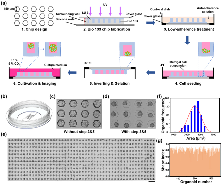
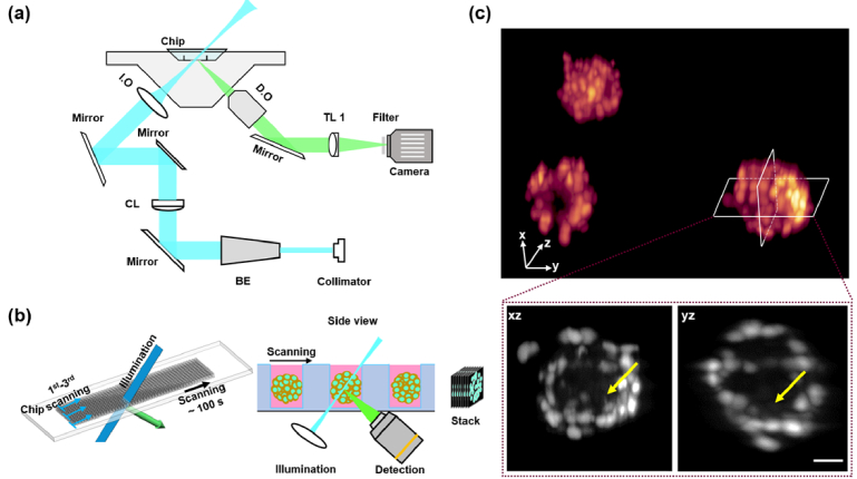
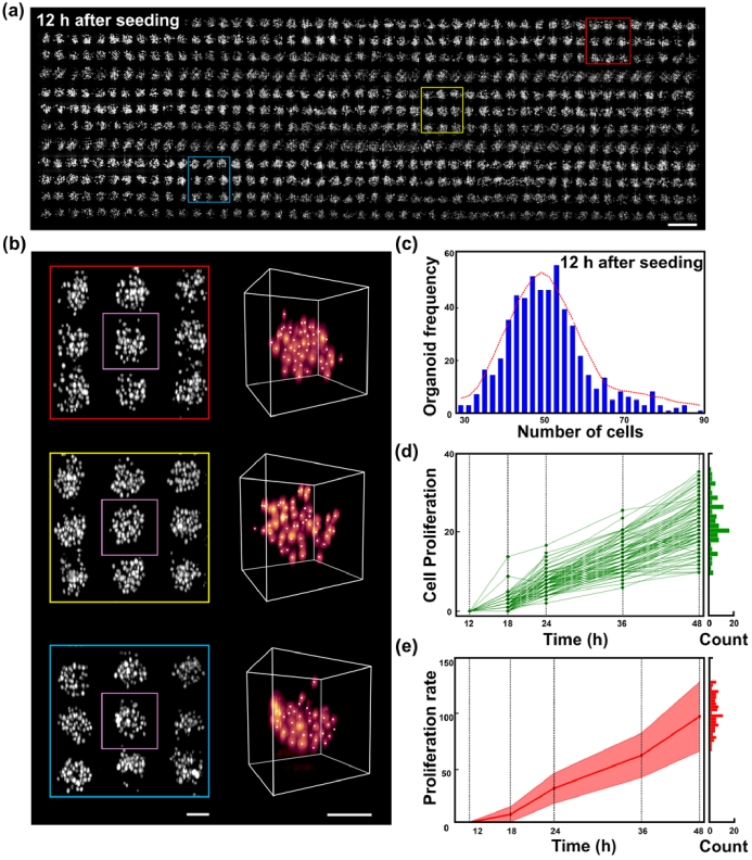
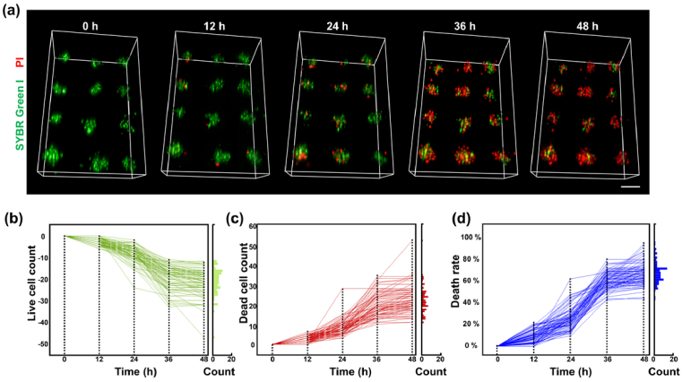
Light sheet microscopy combined with a microchip is an emerging tool in biomedical research that notably improves efficiency. However, microchip-enhanced light-sheet microscopy is limited by noticeable aberrations induced by the complex refractive indices in the chip. Herein, we report a droplet microchip that is specifically engineered to be capable of large-scale culture of 3D spheroids (over 600 samples per chip) and has a polymer index matched to water (difference <1%). When combined with a lab-built open-top light-sheet microscope, this microchip-enhanced microscopy technique allows 3D time-lapse imaging of the cultivated spheroids with ∼2.5-µm single-cell resolution and a high throughput of ∼120 spheroids per minute. This technique was validated by a comparative study on the proliferation and apoptosis rates of hundreds of spheroids with or without treatment with the apoptosis-inducing drug Staurosporine.


Conflict of interest statement

The authors declare no conflicts of interest.

Figures

Fig. 1.
Fig. 1.
Design, fabrication protocol and performance of the Bio 133-based micro-chip. (a) Illustration of each step of the protocol from chip design to chip fabrication, to cell seeding, to 3D culture. (b) Schematic diagram of the chip. A Bio 133 layer is attached to the cover glass bottom of a confocal cell culture dish. (c) Cells would be attached to the bottom and sidewall without steps 3&5. (d) Cells would eventually form spherical spheroids in the chip with steps 3&5. (e) A stitched 2D image of a chip containing 600 spheroids. (f) The 2D area distribution of the spheroids in (e). (g) The shape index distribution of the spheroids in (e). Scale bars are 150 µm in (c) and (d), and 500 µm in (e).
Fig. 2.
Fig. 2.
The open-top LSFM system. (a) Schematic showing the open-top LSFM setup. The chip is fixed on a horizontal moving stage. The illumination and detection parts are tilted at an angle of 45° to the chip. I.O: illumination objective; D.O: detection objective; BE: beam expander; CL: cylindrical lens; TL: tube lens. (b) Illustration of light-sheet scanning process (left) and corresponding side view (right). (c) Representative 3D images of the spheroids stained with SYBR Green I, where xy and yz planes are cropped to show inner details. Yellow arrows indicate cavity structure inside the spheroid. Scale bar is 25 µm.
Fig. 3.
Fig. 3.
Large-scale 3D imaging and analysis of spheroids in chip. (a) High-throughput light sheet fluorescence image of a chip with 600 cell spheroids at 12 h post-seeding. Cells are stained with SYBR green I. (b) ROIs in (a), and related 3D reconstruction of cells. (c) Cell number distribution of the spheroids in (a). (d) Changes in cell number at 12, 18, 24, 36 and 48 h after cell seeding in 100 spheroids. (e) Cell proliferation rate at 12, 18, 24, 36 and 48 h after cell seeding in 100 spheroids. The histograms in (d) and (e) indicate distribution of cell proliferation and proliferation rate at the end of the experiment, respectively. Scale bars are 200 µm in (a), and 50 µm in (b).
Fig. 4.
Fig. 4.
Time-lapse imaging and analysis of spheroid apoptosis induced by STS. (a) Representative 3D reconstruction of spheroids 0, 12, 24, 36 and 48 h after STS treatment. The green channel and the red channel represent live cells stained with SYBR Green I and dead cells stained with PI, respectively. (b-c) Changes in cell number over time for live cells (b) and dead cells (c). (d) Changes in cell death following STS treatment. The histograms in (b-d) indicate distribution of live cell number, dead number and death rate at the end of the experiment, respectively. Scale bars, 100 µm.

References

    1. Badillo-Mata J. A., Camacho-Villegas T. A., Lugo-Fabres P. H., “3D cell culture as tools to characterize rheumatoid arthritis signaling and development of new treatments,” Cells 11(21), 3410 (2022).10.3390/cells11213410 - DOI - PMC - PubMed
    1. Gamboa C. M., Wang Y. J., Xu H. T., Kalemba K., Wondisford F. E., Sabaawy H. E., “Optimized 3D culture of hepatic cells for liver organoid metabolic assays,” Cells 10(12), 3280 (2021).10.3390/cells10123280 - DOI - PMC - PubMed
    1. Olofsson K., Carannante V., Ohlin M., Frisk T., Kushiro K., Takai M., Lundqvist A., Onfelt B., Wiklund M., “Acoustic formation of multicellular tumor spheroids enabling on-chip functional and structural imaging,” Lab Chip 18(16), 2466–2476 (2018).10.1039/C8LC00537K - DOI - PubMed
    1. Rasouli R., Tabrizian M., “Rapid formation of multicellular spheroids in boundary-driven acoustic microstreams,” Small 17(39), 2101931 (2021).10.1002/smll.202101931 - DOI - PubMed
    1. Shao C. M., Chi J. J., Zhang H., Fan Q. H., Zhao Y. J., Ye F. F., “Development of cell spheroids by advanced technologies,” Adv. Mater. Technol. 5(9), 16 (2020).10.1002/admt.202000183 - DOI

LinkOut - more resources