. 2023 Apr 21;9(16):eadf4049.
doi: 10.1126/sciadv.adf4049. Epub 2023 Apr 21.

Truly form-factor-free industrially scalable system integration for electronic textile architectures with multifunctional fiber devices

Affiliations

Truly form-factor-free industrially scalable system integration for electronic textile architectures with multifunctional fiber devices

Sanghyo Lee et al. Sci Adv. .

Abstract

An integrated textile electronic system is reported here, enabling a truly free form factor system via textile manufacturing integration of fiber-based electronic components. Intelligent and smart systems require freedom of form factor, unrestricted design, and unlimited scale. Initial attempts to develop conductive fibers and textile electronics failed to achieve reliable integration and performance required for industrial-scale manufacturing of technical textiles by standard weaving technologies. Here, we present a textile electronic system with functional one-dimensional devices, including fiber photodetectors (as an input device), fiber supercapacitors (as an energy storage device), fiber field-effect transistors (as an electronic driving device), and fiber quantum dot light-emitting diodes (as an output device). As a proof of concept applicable to smart homes, a textile electronic system composed of multiple functional fiber components is demonstrated, enabling luminance modulation and letter indication depending on sunlight intensity.


Figures
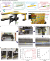
Fig. 1.
Fig. 1.. Automated weaving process for the textile electronic system.
(A) Schematic illustration of the F-PD as a sensing component, F-SC as an energy storage component, F-FET as an electrical driving component, and F-QLED as a lighting component. (B) Schematic illustration of the programmable weaving process to integrate the fiber components into the textile. The fiber devices and conductive thread are inserted in the weft and the weft/warp directions, respectively, corresponding to the predesigned circuit diagram. (C) Photographs display the locations and movement of a shuttle and reed in the five steps during one cycle of weaving: idle status, picking a weft thread, insertion of a weft thread, battening by pushing the reed, and recovery of the reed’s position. (D) Photographs showing the change of the reed’s position for the battering/recovery process. The travel length of the reed in this system is 15 cm. (E) Duration of one cycle, speed of the reed, and (F) battening force at the various grades, which are speed units used in the program of the machine.
Fig. 2.
Fig. 2.. Automated interconnection process for the textile electronic system by laser welding.
(A) Illustration of the automation system for dispensing conductive silver adhesive and optical image of the adhesive after dispensing on the targeted position. Scale bar, 1 mm. (B) Illustration of programmable laser illumination on dispensed adhesive (2.5 W, 1 s). The graph shows the temperature profile of the adhesive as a function of laser curing time. IR, infrared. (C) Illustration of the functional textile with electrical layout and an optical image of the adhesive after laser soldering. Scale bar, 1 mm. (D) Experimental evaluation of the mechanical properties of solidified conductive adhesive. (E) Electrical resistance of a series connection (thread–laser weld adhesive–thread) in the textile during abrasion test with respect to the number of abrasive cycling operation.
Fig. 3.
Fig. 3.. Evaluation of fiber devices after automated integration.
Photographs of integrated (A) F-PDs, (B) F-SCs, (C) F-FETs, and (D) F-QLEDs into the textile in the weft direction. The inset in each photograph is a schematic illustration of the structure of the corresponding device. Characteristics of functional fiber components in the textile before and after automated integration. (E) Photocurrent of F-PDs at a VDS of 10 V under the 365-nm UV irradiation with an intensity of 1 mW. (F) Cyclic voltammetry curves of F-SCs with a scan rate of 100 mV/s. (G) Transfer curves and gate current (IG) of F-FETs with W/L of 80/20 μm at a VDS of 4 V. (H) Current and luminance of F-QLED as a function of the driving voltage.
Fig. 4.
Fig. 4.. Photosensing, energy storage, electrical driving, and lighting textile fabricated by automated integration.
(A) Sensing textile with F-PDs and a diagram of connections with a signal controller. (B) Photographs demonstrating UV light detection in multiple points of the photosensing textile. (C) Electrical configuration of energy storage textile. F-SCs are connected to provide 5 V of output voltage. (D) Cyclic voltammetry curves of 18 F-SCs to validate the energy storage performance after integration. (E) Charging and discharging properties of multiple F-SCs connected in series at a current of 0.7 mA. (F) Twenty-one and 29 commercial red LEDs, powered by energy storage textile with an output of 5 V. (G) Time-domain profile of output voltage for an array of F-SCs, which is connected to commercial white LEDs. (H and I) Integration of five F-FETs into the textile. Scale bars, 5 and 1 cm, respectively. (J) Highly magnified photograph showing two F-FETs after parallel interconnection of gate, source, and drain electrodes with conductive thread by laser soldering. Scale bar, 1 cm. (K) F-FETs in the textile are connected to a commercial LED, a signal controller, and a power supply. The signal controller is wired up to the gate electrode of F-FETs, controlling the brightness of the LED. Scale bar, 5 cm. (L) Profile of the gate voltage sweeping in the time domain for operating a white LED. The inset photographs show the brightness modulation of the LED as a function of gate voltage in the range from 0 to 5 V, at a VDS of 5 V. Photographs show F-QLEDs woven in the textile for (M) red, (N) green, and (O) blue emission. Characteristics of (P) luminance and (Q) electroluminescence on red, green, and blue F-QLEDs. Scale bars, 1 cm. a.u., arbitrary units.
Fig. 5.
Fig. 5.. Textile electronic system for light modulation and letter indication corresponding to the intensity of incident sunlight.
(A) Schematic of the textile system with a combination of F-PDs, F-SCs, F-FETs, and F-QLEDs, for generating environmental information by light modulation. (B) Photograph of the textile electronic system designed to modulate light emission corresponding to the intensity of incident sunlight. Scale bar, 10 cm. (C) Photograph of 16 F-SCs array and 6 F-FETs. F-SCs and F-FETs connected in series and in parallel, respectively. A signal controller is connected at the gate electrodes of F-FETs via a conductive thread. Scale bar, 2 cm. (D) Transfer curves of F-FETs (6 transistors in parallel) powered with either F-SCs (16 supercapacitors in series) or an external dc power supply to the drain electrode. (E) Photograph of the F-FETs and F-QLEDs connections. Scale bar, 2 cm. (F) Brightness profile of F-QLED pixels driven by IDS of F-FETs as a function of VGS. The anode of the F-QLED is connected to the source of the F-FET, and a voltage of 16 V is applied to the drain electrode of the F-FET. (G) Operation chart of light modulation in four phases: idle, sensing, control, and output (light). (H) Output signals in the time domain of F-PD, signal controller, F-FET, and F-QLED, corresponding to the intensity of UV light arising from a solar simulator (14.7% UV in the generated light) and a 50% UV filter. (I) Photographs of the textile system showing the change of F-QLED brightness corresponding to the incident UV light (0, 50, and 100%). Scale bars, 1 cm. Photographs of the textile electronic system with pixelated F-QLEDs (5 × 3) displaying the information of (J) alphabetical and (K) numeric character corresponding to the incident UV light (0, 50, and 100%), Scale bars, 1 cm.

References

    1. S. Sundaram, P. Kellnhofer, Y. Li, J. Y. Zhu, A. Torralba, W. Matusik, Learning the signatures of the human grasp using a scalable tactile glove. Nature 569, 698–702 (2019). - PubMed
    1. X. Shi, Y. Zuo, P. Zhai, J. Shen, Y. Yang, Z. Gao, M. Liao, J. Wu, J. Wang, X. Xu, Q. Tong, B. Zhang, B. Wang, X. Sun, L. Zhang, Q. Pei, D. Jin, P. Chen, H. Peng, Large-area display textiles integrated with functional systems. Nature 591, 240–245 (2021). - PubMed
    1. X. Tian, P. M. Lee, Y. J. Tan, T. L. Y. Wu, H. Yao, M. Zhang, Z. Li, K. A. Ng, B. C. K. Tee, J. S. Ho, Wireless body sensor networks based on metamaterial textiles. Nat. Electron. 2, 243–251 (2019).
    1. X. Yu, Z. Xie, Y. Yu, J. Lee, A. Vazquez-Guardado, H. Luan, J. Ruban, X. Ning, A. Akhtar, D. Li, B. Ji, Y. Liu, R. Sun, J. Cao, Q. Huo, Y. Zhong, C. M. Lee, S. Y. Kim, P. Gutruf, C. Zhang, Y. Xue, Q. Guo, A. Chempakasseril, P. Tian, W. Lu, J. Y. Jeong, Y. J. Yu, J. Cornman, C. S. Tan, B. H. Kim, K. H. Lee, X. Feng, Y. Huang, J. A. Rogers, Skin-integrated wireless haptic interfaces for virtual and augmented reality. Nature 575, 473–479 (2019). - PubMed
    1. M. Wang, Z. Yan, T. Wang, P. Cai, S. Gao, Y. Zeng, C. Wan, H. Wang, L. Pan, J. Yu, S. Pan, K. He, J. Lu, X. Chen, Gesture recognition using a bioinspired learning architecture that integrates visual data with somatosensory data from stretchable sensors. Nat. Electron. 3, 563–570 (2020).