. 2023 Apr 19;8(2):166.
doi: 10.3390/biomimetics8020166.

Structural Mechanical Properties of 3D Printing Biomimetic Bone Replacement Materials

Affiliations

Structural Mechanical Properties of 3D Printing Biomimetic Bone Replacement Materials

Xueman Lv et al. Biomimetics (Basel). .

Abstract

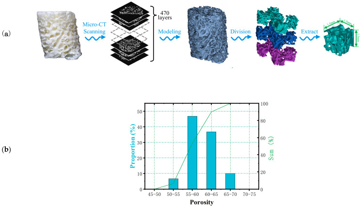
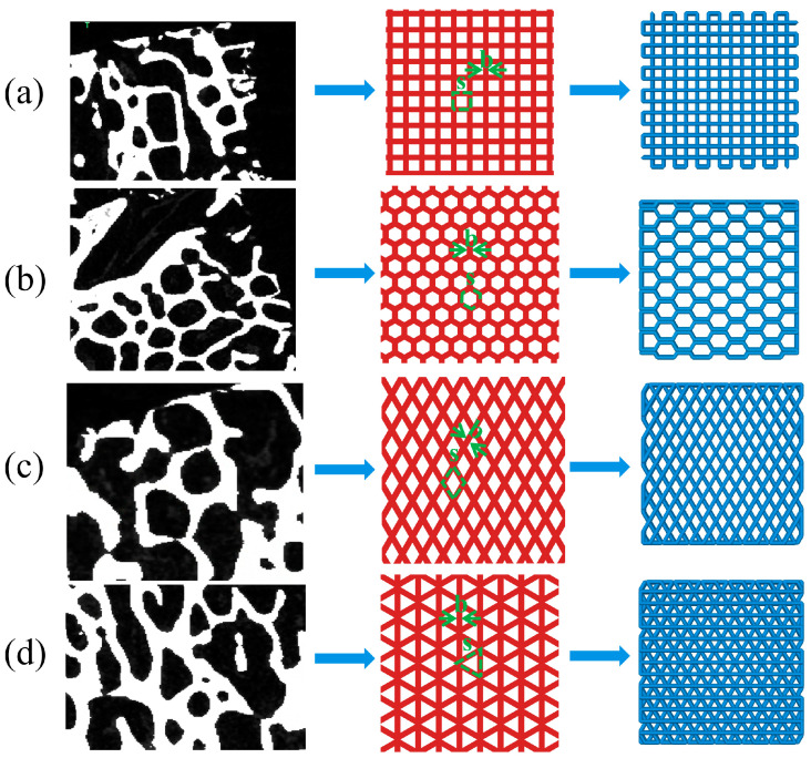
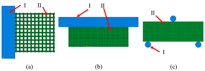
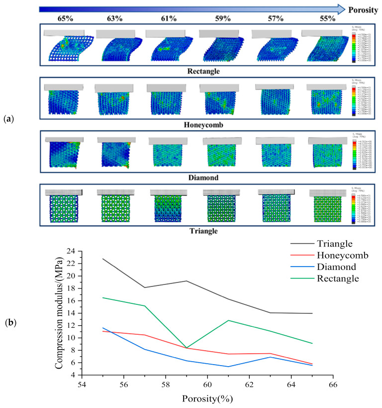
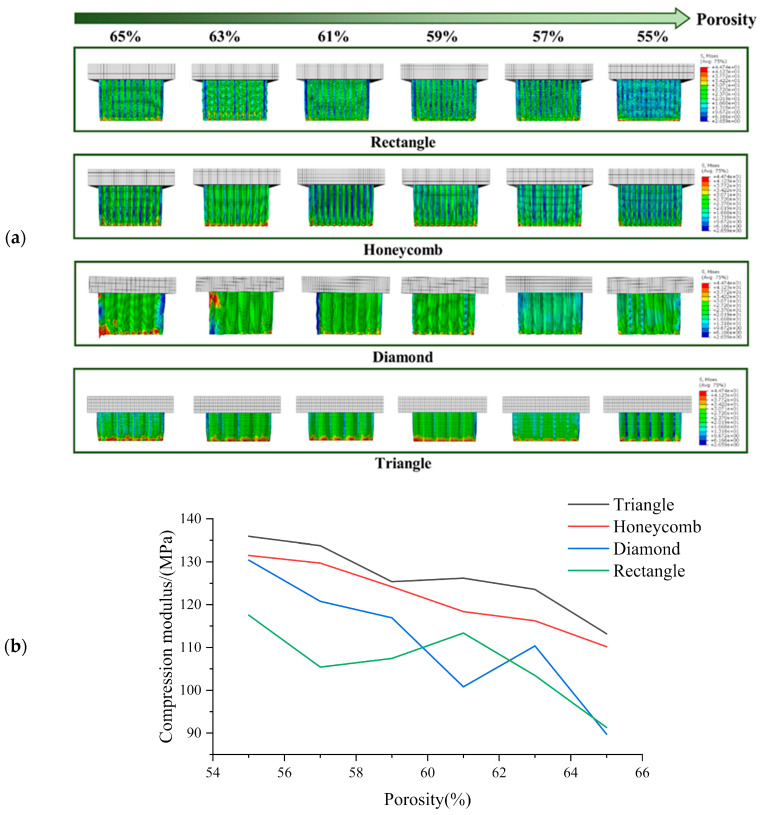
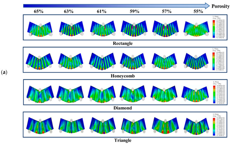
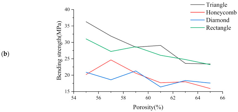
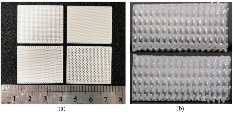
One of the primary challenges in developing bone substitutes is to create scaffolds with mechanical properties that closely mimic those of regenerated tissue. Scaffolds that mimic the structure of natural cancellous bone are believed to have better environmental adaptability. In this study, we used the porosity and thickness of pig cancellous bone as biomimetic design parameters, and porosity and structural shape as differential indicators, to design a biomimetic bone beam scaffold. The mechanical properties of the designed bone beam model were tested using the finite element method (FEM). PCL/β-TCP porous scaffolds were prepared using the FDM method, and their mechanical properties were tested. The FEM simulation results were compared and validated, and the effects of porosity and pore shape on the mechanical properties were analyzed. The results of this study indicate that the PCL/β-TCP scaffold, prepared using FDM 3D printing technology for cancellous bone tissue engineering, has excellent integrity and stability. Predicting the structural stability using FEM is effective. The triangle pore structure has the most stability in both simulations and tests, followed by the rectangle and honeycomb shapes, and the diamond structure has the worst stability. Therefore, adjusting the porosity and pore shape can change the mechanical properties of the composite scaffold to meet the mechanical requirements of customized tissue engineering.

Keywords: 3D printing; PCL; TCP; bone scaffold; finite element method; mechanical property analysis.


Conflict of interest statement

The authors declare no conflict of interest.

Figures

Figure 1
Figure 1
(a) Extraction process and (b) the proportion of pores in bone trabecular unit model.
Figure 2
Figure 2
Extraction and arrange ment of bionic bone scaffold filling structure (a) rectangle (b) honeycomb (c) diamond (d) triangle.
Figure 3
Figure 3
ABAQUS compression experimental assembly drawing where I is the rigid body and II is the samples: (a) Transverse compression; (b) axial compression; (c) three-point bending experimental assembly drawing.
Figure 4
Figure 4
(a) Transverse compression test simulation results and (b) Compression modulus of each sample in transverse compression test with different porosity.
Figure 5
Figure 5
(a) Axial compression test simulation results and (b) Compression modulus of each sample in axial compression test with different porosity.
Figure 6
Figure 6
(a) Three-point bending test simulation results and (b) Three-point bending results of each sample with different porosity.
Figure 6
Figure 6
(a) Three-point bending test simulation results and (b) Three-point bending results of each sample with different porosity.
Figure 7
Figure 7
Photo of 3D printed bionic scaffold samples: (a) Photo of the pore shape of the samples; (b) Profile view of the print samples.
Figure 8
Figure 8
The actual size of 30%β-TCP/PCL scaffolds with different porosity.
Figure 9
Figure 9
Transverse compression deformation maps of four samples with different porosity.
Figure 10
Figure 10
Deformation figure in axial compression direction of four samples with different porosity.
Figure 11
Figure 11
(a) Three-point bending resistance–displacement diagram of square pore with different porosity; (b) Ultimate bearing resistance diagram in three-point bending test of four samples with different porosity.

Similar articles

Cited by

References

    1. Glowacki J. The Law of Bone Remodelling. Plast. Reconstr. Surg. 1988;82:717. doi: 10.1097/00006534-198810000-00036. - DOI
    1. Finkemeier C.G. Bone-Grafting and Bone-Graft Substitutes. J. Bone Jt. Surg. Am. 2002;84:454–464. doi: 10.2106/00004623-200203000-00020. - DOI - PubMed
    1. Mishra R., Bishop T., Valerio I.L., Fisher J.P., Dean D. The potential impact of bone tissue engineering in the clinic. Regen. Med. 2016;11:571–587. doi: 10.2217/rme-2016-0042. - DOI - PMC - PubMed
    1. Winkler T., Sass F.A., Duda G.N., Schmidt-Bleek K. A review of biomaterials in bone defect healing, remaining shortcomings and future opportunities for bone tissue engineering: The unsolved challenge. Bone Jt. Res. 2018;7:232–243. doi: 10.1302/2046-3758.73.BJR-2017-0270.R1. - DOI - PMC - PubMed
    1. Amini A.R., Laurencin C.T., Nukavarapu S.P. Bone Tissue Engineering: Recent Advances and Challenges. Crit. Rev. Biomed. Eng. 2012;40:363–408. doi: 10.1615/CritRevBiomedEng.v40.i5.10. - DOI - PMC - PubMed

LinkOut - more resources