. 2023 May;617(7960):299-305.
doi: 10.1038/s41586-023-05888-x. Epub 2023 Apr 26.

Near-frictionless ion transport within triazine framework membranes

Affiliations

Near-frictionless ion transport within triazine framework membranes

Peipei Zuo et al. Nature. 2023 May.

Abstract

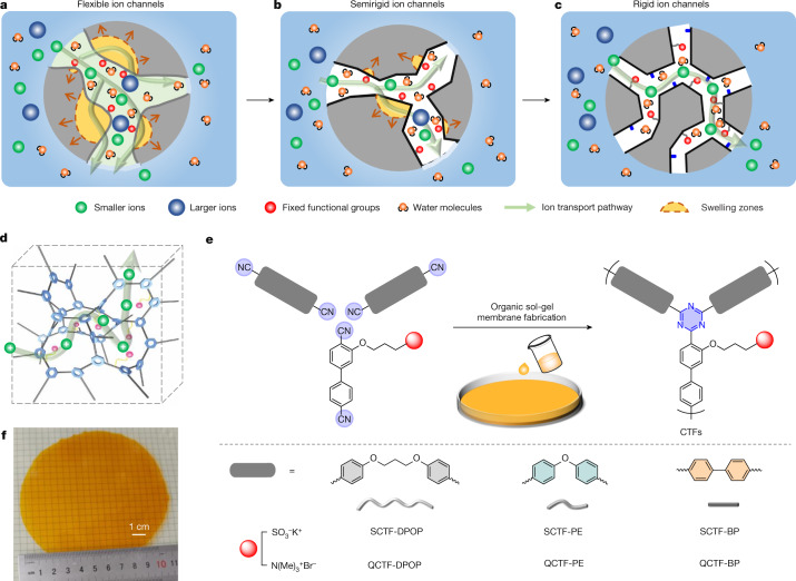
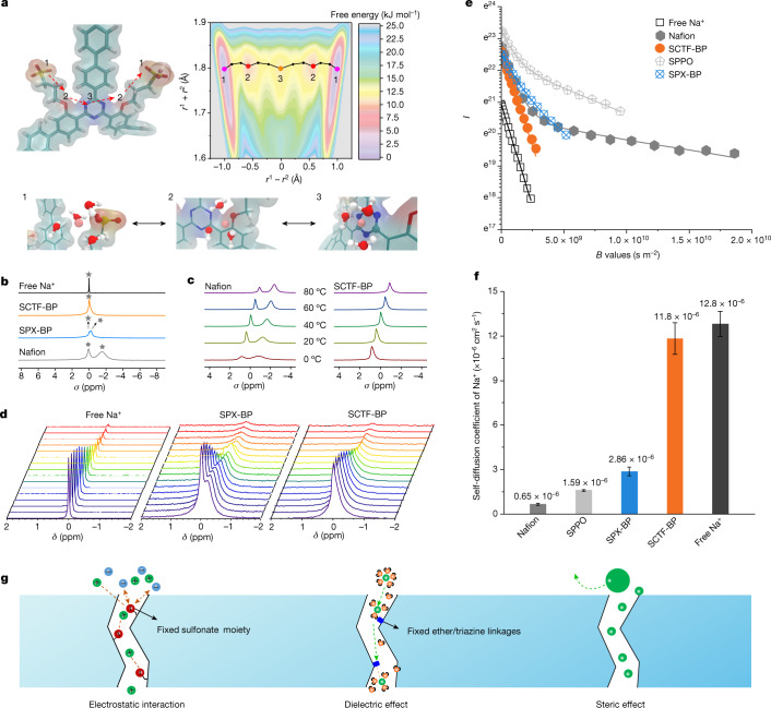
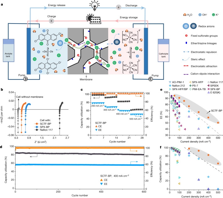
The enhancement of separation processes and electrochemical technologies such as water electrolysers1,2, fuel cells3,4, redox flow batteries5,6 and ion-capture electrodialysis7 depends on the development of low-resistance and high-selectivity ion-transport membranes. The transport of ions through these membranes depends on the overall energy barriers imposed by the collective interplay of pore architecture and pore-analyte interaction8,9. However, it remains challenging to design efficient, scaleable and low-cost selective ion-transport membranes that provide ion channels for low-energy-barrier transport. Here we pursue a strategy that allows the diffusion limit of ions in water to be approached for large-area, free-standing, synthetic membranes using covalently bonded polymer frameworks with rigidity-confined ion channels. The near-frictionless ion flow is synergistically fulfilled by robust micropore confinement and multi-interaction between ion and membrane, which afford, for instance, a Na+ diffusion coefficient of 1.18 × 10⁻⁹ m2 s-1, close to the value in pure water at infinite dilution, and an area-specific membrane resistance as low as 0.17 Ω cm2. We demonstrate highly efficient membranes in rapidly charging aqueous organic redox flow batteries that deliver both high energy efficiency and high-capacity utilization at extremely high current densities (up to 500 mA cm-2), and also that avoid crossover-induced capacity decay. This membrane design concept may be broadly applicable to membranes for a wide range of electrochemical devices and for precise molecular separation.


Conflict of interest statement

The authors declare no competing interests.

Figures

Fig. 1
Fig. 1. Schematic illustrations showing existing and proposed ion-selective polymer membranes with varying ion channels.
a, Membranes with flexible ion channels. These contain microphase-separated morphology derived from the assembly of hydrophilic ion-conductive moieties and hydrophobic flexible-polymer backbones, represented by Nafion. b, Ion-selective microporous membranes with semirigid ion channels. The channels are formed by intrinsic micropores resulting from inefficient polymer chain packing, represented by polymers of intrinsic microporosity and their derivatives. To render the membrane ion conductive, functional moieties are incorporated during postsynthetic modification. Membranes may age over time and swell in water. c,d, Our proposed membranes with rigid ion channels (c). These are expected to build from bottom-up synthesis and via swelling-resistant 3D polymer frameworks (d). Pore architecture and chemistry are tuned for rapid and selective ion transport. e,f, Preparation of stand-alone CTF membranes via a superacid-catalysed organic sol-gel reaction from functional aromatic nitrile monomers (e). CTF membranes have a controlled number of ion-conductive moieties inside membrane pores and a covalent network structure. Image (f) shows a free-standing CTF membrane with a diameter of over 10 cm. Structure rigidity and microporosity of the CTF membrane can be regulated by designing variable structural units, as demonstrated at bottom right, from flexible to very rigid.
Fig. 2
Fig. 2. Characterization of negatively charged CTF membranes (SCTF).
a,b, Schematic representation of the chain structure of SCTF-PE (a) and SCTF-BP (b), with a flexible and a very rigid chain, respectively (left). 3D view of the amorphous cells of SCTF-PE and SCTF-BP membranes (middle). Images of aged cells shown on the right. Red shading represents isolated free-volume elements and green shading represents interconnected micropores. c, CO2 uptake (at 273 K) of SCTF samples compared with that of PIM-1. d, Swelling ratio plotted as a function of IEC (the content of charged functional groups, in mmol g−1) for SCTF-BP, Nafion, SPX-BP and hydrophilic PIM membranes. e, K+ conductivity plotted as a function of hydration number for SCTF-BP, Nafion, SPX-BP and SPPO membranes. Each dot represents measurement at a separate temperature: from left to right, 30–70 °C. Dashed lines and shading are a visual guide only. d,e, The values shown can be found in Supplementary Tables 1 and 3. STP, standard temperature and pressure.
Fig. 3
Fig. 3. Ion transport across the SCTF-BP membrane.
a, Modelling and calculation of free energy for the transport of K+ across the SCTF-BP membrane matrix; the path 1-2-3-2-1 has the lowest free energy for K+ transport. Insets demonstrate the specific interaction between K+ and SCTF-BP chains in positions 1, 2 and 3. b, ssNMR measured for membrane samples of SCTF-BP, SPX-BP and Nafion. 100 mM NaCl in water was used as control, with membrane samples immersed in 0.1 M NaCl solution (Na+ rather than K+ because of improved NMR sensitivity). c, 23Na ssNMR for Nafion and SCTF-BP membranes in 0.1 M NaCl solution at varying temperature. d, PFG–NMR spectra collected for 0.1 M NaCl solution and membrane samples of SPX-BP and SCTF-BP. Spectra for Nafion and SPPO are given in Supplementary Fig. 20. e,f, Plot of PFG–NMR signal intensity versus magnetic gradient strength (e, B values) and diffusion coefficients derived from PFG–NMR for Na+ in water, SCTF-BP, SPX-BP, Nafion and SPPO membrane samples (f). Echo profiles are fitted to the Stejskal–Tanner equation. I denotes the echo height at a given gradient strength; B denotes the product of all parameters before the diffusion coefficient (D) of the Stejskal–Tanner equation (that is, equation 9 in Supplementary Information); r1 and r2 denote the distance between the potassium ion and the geometric centre of two adjacent sulfonate groups. Error bars (s.d.) are derived from three measurements based on three individual membrane samples. g, Schematic showing electrostatic interaction and dielectric and steric effects during ion transport enabled by the negatively charged CTF membrane.
Fig. 4
Fig. 4. SCTF-BP membrane enables rapid charging of aqueous alkaline quinone flow battery.
a, Schematic illustrating an alkaline quinone flow battery assembled with the SCTF-BP membrane, and conduction of K+ ions across the membrane matrix. The catholyte is ferrocyanide and the anolyte molecule is DHAQ. b, EIS spectra measured in cells assembled with SCTF-BP, SPX-BP and Nafion 117 membrane, respectively. The grey line represents the EIS spectrum of the cell without a membrane. c, Coulombic efficiency (CE), capacity utilization and EE of the cell assembled with SCTF-BP at varying current density. For each current density, seven repetitions were performed to ensure accuracy. Fluctuations were observed only when current density was switched. d, Galvanostatic cycling at a current density of 400 mA cm−2 for cells assembled with a SCTF-BP membrane. bd, Electrolyte concentration 0.4 M. e,f, Energy efficiency (e) and capacity utilization (f) of quinone flow batteries assembled with commercial, PIM and SCTF-BP membranes are plotted as functions of current density. Symbols shown in inset in e apply also to f. e,f, Dashed lines and shading are a visual guide only; detailed values provided in Supplementary Table 5.

References

    1. Salvatore DA, et al. Designing anion exchange membranes for CO2 electrolysers. Nat. Energy. 2021;6:339–348. doi: 10.1038/s41560-020-00761-x. - DOI
    1. Lagadec MF, Grimaud A. Water electrolysers with closed and open electrochemical systems. Nat. Mater. 2020;19:1140–1150. doi: 10.1038/s41563-020-0788-3. - DOI - PubMed
    1. Jiao K, et al. Designing the next generation of proton-exchange membrane fuel cells. Nature. 2021;595:361–369. doi: 10.1038/s41586-021-03482-7. - DOI - PubMed
    1. Tang H, et al. Fuel cells with an operational range of –20 °C to 200 °C enabled by phosphoric acid-doped intrinsically ultramicroporous membranes. Nat. Energy. 2022;7:153–162. doi: 10.1038/s41560-021-00956-w. - DOI
    1. Xiong P, Zhang L, Chen Y, Peng S, Yu G. A chemistry and microstructure perspective on ion-conducting membranes for redox flow batteries. Angew. Chem. Int. Ed. Engl. 2021;60:24770–24798. doi: 10.1002/anie.202105619. - DOI - PubMed

Publication types