Review
. 2023 Apr 18;12(8):2946.
doi: 10.3390/jcm12082946.

Update on Shoulder Arthroplasties with Emphasis on Imaging

Affiliations
Review

Update on Shoulder Arthroplasties with Emphasis on Imaging

Jennifer S Weaver et al. J Clin Med. .

Abstract

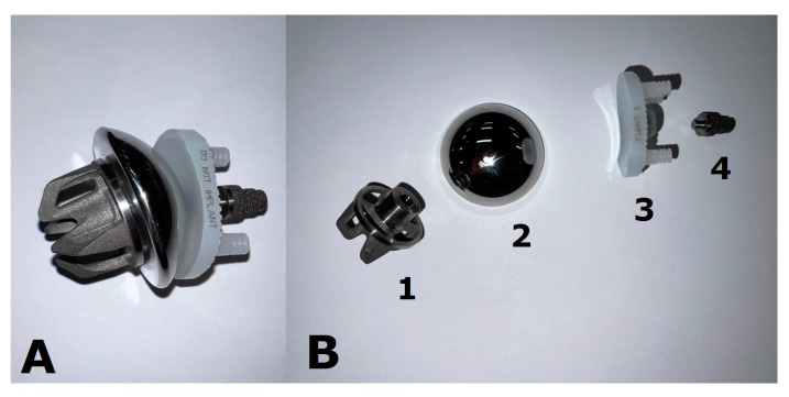
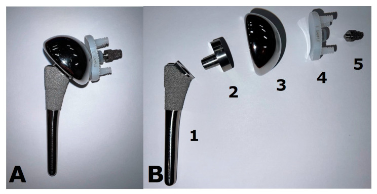
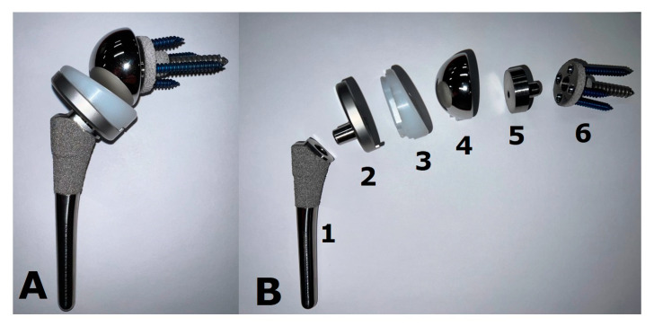
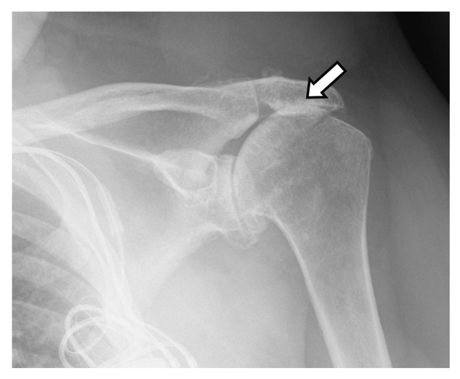
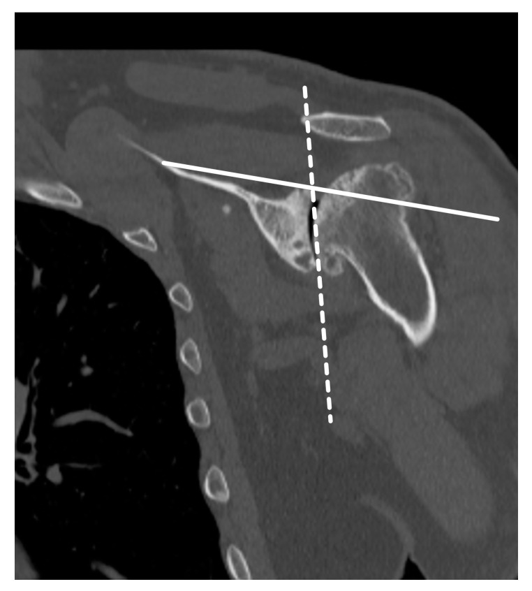
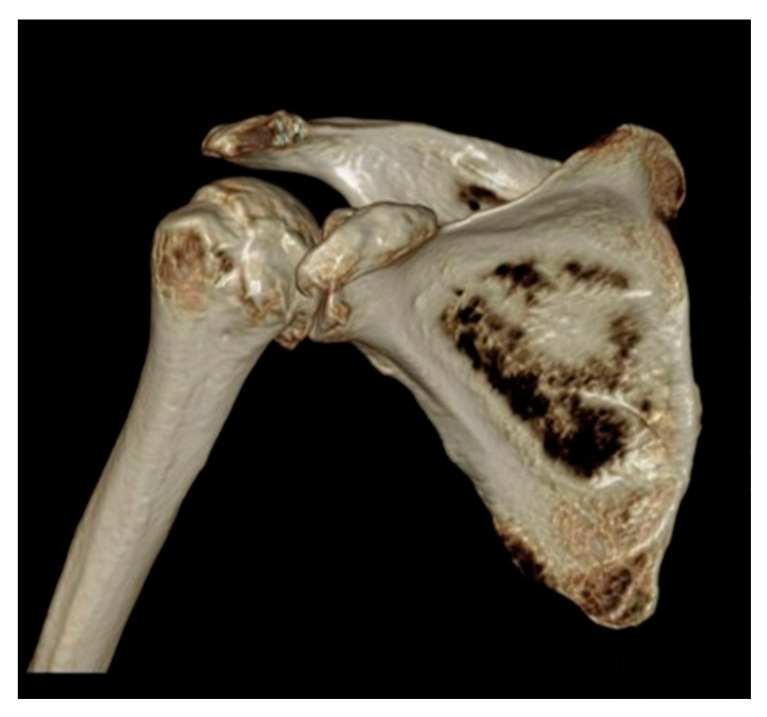
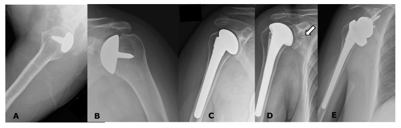
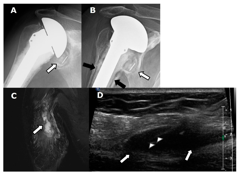
Shoulder pain and dysfunction may significantly impact quality of life. If conservative measures fail, advanced disease is frequently treated with shoulder arthroplasty, which is currently the third most common joint replacement surgery following the hip and knee. The main indications for shoulder arthroplasty include primary osteoarthritis, post-traumatic arthritis, inflammatory arthritis, osteonecrosis, proximal humeral fracture sequelae, severely dislocated proximal humeral fractures, and advanced rotator cuff disease. Several types of anatomic arthroplasties are available, such as humeral head resurfacing and hemiarthroplasties, as well as total anatomic arthroplasties. Reverse total shoulder arthroplasties, which reverse the normal ball-and-socket geometry of the shoulder, are also available. Each of these arthroplasty types has specific indications and unique complications in addition to general hardware-related or surgery-related complications. Imaging-including radiography, ultrasonography, computed tomography, magnetic resonance imaging, and, occasionally, nuclear medicine imaging-has a key role in the initial pre-operative evaluation for shoulder arthroplasty, as well as in post-surgical follow-up. This review paper aims to discuss important pre-operative imaging considerations, including rotator cuff evaluation, glenoid morphology, and glenoid version, as well as to review post-operative imaging of the various types of shoulder arthroplasties, to include normal post-operative appearances as well as imaging findings of complications.

Keywords: arthritis; arthroplasty; computed tomography; magnetic resonance imaging; radiography; rotator cuff; shoulder; ultrasound.


Conflict of interest statement

The authors declare no conflict of interest.

Figures

Figure 1
Figure 1
Example of a stemless shoulder implant. This prosthesis is shown (A) assembled and (B) deconstructed. The humeral head is secured to the cut humeral surface via an “anchor”, which is fluted and ridged to facilitate osseous integration. The anchor (1) and humeral head (2) are joined via a Morse taper. This implant allows for the preservation of humeral bone stock and functions as a resurfacing-type construct. The glenoid component (3) is composed of polyethylene plastic. The top and bottom pegs are cemented in place, while the metal post (4) is press-fit and allows for biologic osseous integration.
Figure 2
Figure 2
Example of an anatomic total shoulder arthroplasty (ATSA) implant. This prosthesis is shown (A) assembled and (B) deconstructed. The stem (1) is porous-coated proximally to allow for biologic osseous integration. The humeral head (3) is fixed to the stem via a Morse-tapered trunnion (2). Note the asymmetry of the trunnion, which allows for matching of the eccentricity of the native humeral head. The glenoid component (4) is composed of polyethylene plastic. The top and bottom pegs are cemented in place, while the metal post (5) is press-fit and allows for biologic osseous integration.
Figure 3
Figure 3
Example of a reverse total shoulder arthroplasty (RTSA) implant. This prosthesis is shown (A) assembled and (B) deconstructed. The stem (1) is porous-coated proximally to allow for biologic osseous integration. The humeral tray (2) is fixed to the stem via a Morse-tapered trunnion and articulates via a polyethylene liner (3). The glenoid base plate/metaglene (6) is porous-coated as well to facilitate osseous integration. It is fixed via a central screw that provides compression and is reinforced with locking screws peripherally. The glenosphere (4) attaches to the glenoid baseplate/metaglene via an eccentric Morse taper (5) to allow for distalization of the components and minimize scapular notching.
Figure 4
Figure 4
Frontal radiograph shows superior migration (white arrow) of the humeral head and developing acetabularization of the acromion in a patient with a full thickness rotator cuff tear.
Figure 5
Figure 5
Coronal T2-weighted fat-saturated magnetic resonance (MR) image shows full thickness superior cuff tear with tendon retraction close to the level of the glenoid (arrow). Bone marrow edema and developing cartilage loss along the humeral head is consistent with developing cuff tear arthritis.
Figure 6
Figure 6
Axial computed tomography (CT) images of the shoulder in three different patients, showing different glenoid morphologies. (A). Walch A. (B). Walch B1. (C). Walch B2.
Figure 7
Figure 7
Axial CT image shows decreased glenoid bone stock (double arrow) due to glenoid erosion and retroversion.
Figure 8
Figure 8
Axial CT images from two different patients (A). Normal glenoid version. (B). Retroversion secondary to glenoid erosion from osteoarthritis. A line (solid white) is drawn from the superior medial scapular border to the center of the glenoid and a line (white dashed) is drawn perpendicular to this on the axial image at or just inferior to the tip of the coracoid. Glenoid version is the angle formed between the perpendicular line (white dashed) and a line (black dotted) drawn along the glenoid articular surface.
Figure 9
Figure 9
Coronal CT image showing glenoid inclination measurement. The inclination angle is measured between a line drawn along the supraspinatus fossa (solid line) and a second line along the glenoid fossa (dotted line).
Figure 10
Figure 10
Three-dimensional reconstructed CT image of the shoulder in a patient with glenohumeral osteoarthritis, for preoperative planning.
Figure 11
Figure 11
Radiographs of several different uncomplicated arthroplasty types. (A). Partial humeral head resurfacing arthroplasty (HHRA). (B). Humeral head resurfacing arthroplasty (HHRA). (C). Hemiarthroplasty (HA). (D). ATSA. Note small radiopaque marker identifying the glenoid component (arrow). (E). RTSA.
Figure 12
Figure 12
Patient with ATSA and periprosthetic joint infection in a patient with shoulder pain. (A). Frontal radiograph shows an ATSA with a small amount of lucency (arrow) around the glenoid component. (B). Frontal radiograph obtained several months later shows worsening lucency (white arrow) along the glenoid component, with new lucency (black arrows) along the bone–cement interface of the humeral component. (C). Coronal T2-weighted, fat-saturated MR image shows lobulated high signal (arrow) throughout the shoulder musculature. (D). Long-axis ultrasound (US) image shows an ovoid soft tissue fluid collection/abscess (arrows), with needle (arrowheads) present during diagnostic aspiration.
Figure 13
Figure 13
(A) Frontal and (B) axillary radiographs show glenoid wear with erosions (arrows) in a patient with an HHRA.
Figure 14
Figure 14
(A). Frontal radiograph in a patient with a normal-appearing ATSA. (B). Frontal radiograph several years later when patient presented with shoulder pain, showing lucency (white arrows) along the glenoid component, with slight superior rotation (black arrow) of the glenoid component within the bone, consistent with glenoid component loosening.
Figure 15
Figure 15
(A) Frontal radiograph in a patient with an RTSA shows lucency (arrows) along the baseplate screws and central screw consistent with loosening. (B). Frontal radiograph in a different patient with RTSA shows lucency (arrows) around the humeral component as well as the bone–cement interface, consistent with loosening. Cortical thinning is also noted along the medial aspect of the distal humeral stem.
Figure 16
Figure 16
(A) Frontal and (B) axillary radiographs in a patient with RTSA showing failure of the humeral component, now separated into two separate pieces (white arrows). There is significant lucency (arrowheads) along the humeral and glenoid components, with cortical thinning, suggesting loosening or infection. The distal tip of the humeral component (curved arrow) breached the cortex and became extraosseous in location.
Figure 17
Figure 17
(A). Frontal radiograph in a patient immediately post-operative from RTSA shows a periprosthetic humeral fracture (arrow). (B). Axillary radiograph in a different patient with RTSA shows a periprosthetic fracture along the humeral stem (arrows).
Figure 18
Figure 18
(A) Scapular Y radiograph in a patient with an RTSA shows an acute acromial fracture (arrow). (B) Frontal and (C) axillary radiographs in a different patient demostrate a healing acromial fracture (arrow) following RTSA.
Figure 19
Figure 19
(A) Axial and (B) parasagittal CT images and (C) a scapular Y radiograph demonstrate a scapular fracture (arrow) following RTSA.
Figure 20
Figure 20
Frontal radiograph shows heterotopic ossification (arrow) along the proximal medial aspect of the humeral stem of an RTSA.
Figure 21
Figure 21
(A). Axillary radiograph shows anterior subluxation of the humeral head (arrow) component of the HA from the glenoid (dotted line) in a patient with subscapularis insufficiency. (B). Long-axis US image (lateral image left, medial image right) in a different patient with an ATSA shows a full thickness subscapularis tendon tear with a retracted tendon stump (arrow).
Figure 22
Figure 22
Dislocated RTSA. (A). Frontal radiograph shows the humeral component displaced superiorly (arrow denotes force direction). (B). Scapular Y view shows the humeral component displaced anteriorly (arrow denotes force direction).
Figure 23
Figure 23
Frontal radiograph in a patient with an RTSA shows fracture/break (arrows) of three of the baseplate screws.
Figure 24
Figure 24
Frontal radiograph in a patient with RTSA shows fracture/break of a screw (curved arrow) as well as superior migration and rotation of the baseplate/metaglene (arrows), now dissociated from the glenoid.
Figure 25
Figure 25
Frontal radiograph in a patient with RTSA shows dissociation of the metaglene/baseplate (white arrow) and the glenosphere (black arrow).
Figure 26
Figure 26
(A) Frontal and (B) axillary radiographs in a patient with RTSA shows dissociation of the glenosphere (arrows) from the metaglene, with displacement of the glenosphere into the posterior soft tissues. (C). The patient was treated via conversion to salvage HA.
Figure 27
Figure 27
(A) Frontal radiograph and (B) coronal and (C) parasagittal CT images in a patient with RTSA show dissociation of the glenosphere from the metaglene/baseplate central screw (arrows).
Figure 28
Figure 28
Frontal radiographs. (A). Immediate post-operative image following RTSA shows incomplete seating of the Morse taper into the baseplate, with resulting asymmetric alignment of the glenosphere (arrow). (B). Patient returned to the operating room for revision of the hardware, with post-operative image showing improved positioning of the Morse taper into the baseplate and improved glenosphere alignment.
Figure 29
Figure 29
Frontal radiographs. Scapular notching grading by using Sirveaux Classification in four different patients with a reverse total shoulder arthroplasty. (A). Grade 1. (B). Grade 2. (C). Grade 3. (D). Grade 4.

References

    1. Papalexis N., Ponti F., Rinaldi R., Peta G., Bruno R., Miceli M., Battaglia M., Marinelli A., Spinnato P. Ultrasound-Guided Treatments for the Painful Shoulder. Curr. Med. Imaging. 2021;18:693–700. doi: 10.2174/1573405617666211206112752. - DOI - PubMed
    1. Lin D.J., Wong T.T., Kazam J.K. Shoulder Arthroplasty, from Indications to Complications: What the Radiologist Needs to Know. Radiographics. 2016;36:192–208. doi: 10.1148/rg.2016150055. - DOI - PubMed
    1. Sharifi A., Siebert M.J., Chhabra A. How to Measure Glenoid Bone Stock and Version and Why It Is Important: A Practical Guide. Radiographics. 2020;40:1671–1683. doi: 10.1148/rg.2020200008. - DOI - PubMed
    1. Lee D.H., Choi Y.S., Potter H.G., Endo Y., Sivakumaran T., Lim T.K., Chun T.J. Reverse total shoulder arthroplasty: An imaging overview. Skelet. Radiol. 2019;49:19–30. doi: 10.1007/s00256-019-03275-0. - DOI - PubMed
    1. Romero B.A., Horneff J.G., 3rd Soft Tissue Management in Shoulder Arthroplasty. Orthop. Clin. N. Am. 2022;53:339–347. doi: 10.1016/j.ocl.2022.02.001. - DOI - PubMed

LinkOut - more resources