. 2023 Apr 27;186(9):1877-1894.e27.
doi: 10.1016/j.cell.2023.03.015.

Molecular mechanisms of stress-induced reactivation in mumps virus condensates

Affiliations

Molecular mechanisms of stress-induced reactivation in mumps virus condensates

Xiaojie Zhang et al. Cell. .

Abstract

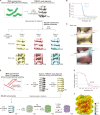
Negative-stranded RNA viruses can establish long-term persistent infection in the form of large intracellular inclusions in the human host and cause chronic diseases. Here, we uncover how cellular stress disrupts the metastable host-virus equilibrium in persistent infection and induces viral replication in a culture model of mumps virus. Using a combination of cell biology, whole-cell proteomics, and cryo-electron tomography, we show that persistent viral replication factories are dynamic condensates and identify the largely disordered viral phosphoprotein as a driver of their assembly. Upon stress, increased phosphorylation of the phosphoprotein at its interaction interface with the viral polymerase coincides with the formation of a stable replication complex. By obtaining atomic models for the authentic mumps virus nucleocapsid, we elucidate a concomitant conformational change that exposes the viral genome to its replication machinery. These events constitute a stress-mediated switch within viral condensates that provide an environment to support upregulation of viral replication.

Keywords: IDR; biomolecular condensates; cryo-electron tomography; cryo-focused ion beam; in-cell structural biology; intrinsically disordered regions; nucleocapsid; persistent infection; phosphorylation; viral replication; whole-cell proteomics.


Conflict of interest statement

Declaration of interests A.A.H. is a founder and scientific advisory board member of Dewpoint Therapeutics and a founder of Caraway Therapeutics. I.P. is an employee of Dewpoint Therapeutics.

Figures

None
Graphical abstract
Figure 1
Figure 1
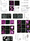
Persistent MuV infection model in HeLa exhibits viral reactivation upon stress (A) Maximum-intensity projection (MIP) of HeLa-MuV cells immuno-stained against the MuV-N protein (cyan). DNA stained with DAPI (gray). Note that persistent MuV infection does not trigger stress granule formation (mCherry-G3BP1 as a marker in magenta). (B) Immuno-RNA FISH of non-stressed HeLa-MuV cells. Central plane confocal images are shown. Intensity profile along the line in the merged panel shows colocalization of viral genomic RNA (yellow) and MuV-N (cyan). y axis is the intensity normalized to 0 and 1 for each channel. (C) Proliferation curves of HeLa-MuV cells in comparison with non-infected HeLa mCherry-G3BP1 cells. Data are shown as mean ± SD (n = 6). (D) MIP of naive HeLa mCherry-G3BP1 cells infected with MuV by transfer of medium from a persistently infected culture, imaged at 2 days post infection. (E) MuV transcription (mRNA) and replication (genomic RNA) levels determined by qPCR targeting different viral genes along the stress course. Dotted lines: starting levels. Data are mean ± SD (n = 3). (F and G) RNA FISH of HeLa-MuV cells at control and indicated stress condition and its quantification. Number of cells analyzed per condition is shown in the plot. Dashed line: median at the start of stress. Box center line: median; box bounds: the first and third quartiles; whiskers: values no further than 1.5 times the distances between the first and third quartiles; statistical significance evaluated using Wilcoxon test, ∗∗p < 0.01. See also Figure S1.
Figure S1
Figure S1
Effect of different stress conditions on viral reactivation in HeLa and U2OS cells, related to Figures 1 and 2 (A) MuV transcription (mRNA) and replication (genomic RNA) levels determined by qPCR targeting the N, P/V, and F genes during the time course of 30 μM As(III) mild stress. Dotted lines: starting levels. Data are mean ± SD (n = 3). (B) RNA FISH of HeLa-MuV cells at 6 h 30 μM As(III) stress (viral genomic RNA detected with single molecular FISH probes (vRNA; yellow)) and quantitative comparison to the non-stress control. Number of cells analyzed for each condition is shown on the plot. Box center line: median; box bounds: the first and third quartiles; whiskers: values no further than 1.5 times the distances between the first and third quartiles; dashed line: median at the start of stress. Statistical significance is evaluated using Wilcoxon test, ∗∗p < 0.01, ∗∗∗p < 0.001, and ∗∗∗∗p < 0.0001. (C) Representative western blot and quantification of MuV N protein levels in the cell culture medium as a proxy for virion release (N_extracellular) and inside cells (N_intracellular) during 24 h of 30 μM As(III) stress or of the non-stress control conditions collected at the same time points. Glyceraldehyde 3-phosphate dehydrogenase (GAPDH) was used as a loading control. Lower bands in N_extracellular are likely degraded forms of N in the medium. Ratio of MuV N_extracellular to N_intracellular (labeled as extra/intra for plots) and levels of N_intracellular (labeled as intra for plots) are normalized to levels at 0 h for each condition. Data are the mean ± SEM (n = 4). Note that levels in both experimental conditions oscillate over 24 h in agreement with Ruggieri et al., with stress inducing a significant increase in released virions at 6 h. Statistical significance is evaluated between the stress and control using two-way ANOVA (Bonferroni’s multiple comparisons) and the label is the adjusted p value. (D) Images and quantification showing the effect of stress on infectious virus production. MIPs of naive HeLa mCherry-G3BP1 cells infected with MuV by transfer of medium from a persistently infected culture (at 0 and 6 h of 30 μM As(III) stress or non-stress control at the same time points), imaged at 2 days post infection. DAPI staining cell nuclei (gray) and anti-MuV N staining viral factories (VFs; cyan) are shown. The sum volume of VFs in the newly infected cells was normalized by the number of cells per image (approximated by the number of nuclei in the field of view), with the fold change of the stress condition over the non-stress control shown in the plot for the two time points (t test; n = 3). See also STAR Methods. (E–G) MIPs of VFs (detected by anti-MuV-N immunostaining) and stress granules (mCherry-G3BP1) in HeLa-MuV cells at 1 h of 30 μM As(III) stress (E; completing data presented in Figure 2B), during 3 h of 0.5 mM As(III) stress (F), and 1 h of heat shock (HS) at 43°C (G). DNA was stained with DAPI (gray). Quantification is provided in Figures 2D–2F. (H) MIPs of MuV factories in persistent MuV infection established in U2OS cells after 6 h of 1 mM As(V) stress in comparison with control and their quantification. Violin plots as defined above. Number of cells per condition is indicated. Statistical significance is evaluated using Wilcoxon tests.
Figure 2
Figure 2
Persistent MuV replication factories coarsen under different stress conditions (A and B) MIPs of MuV factories (VFs; detected by anti-MuV-N immunostaining) and stress granules (mCherry-G3BP1) in HeLa-MuV cells during the time course of acute and mild stress. (C–F) Quantification of data in (A) and (B) and two additional stress conditions for VF size and number per cell. Number of cells per condition is indicated. HS, heat shock. Violine plot details as above. Statistical significance evaluated using Wilcoxon test, ∗∗p < 0.01, ∗∗∗p < 0.001, and ∗∗∗∗p < 0.0001. (G) Effect of 15 min 1,6-hexanediol (1,6-Hex) treatment on authentic MuV factories over the time course of stress. HeLa-MuV cells were stressed to the indicated time points and then incubated with 1,6-Hex or water as control. Central plane images are shown. Upper left corresponds to the number of cells per condition; upper right is the average number of VFs larger than 2 μm in diameter per cell at each condition. See also Figure S1.
Figure 3
Figure 3
The MuV phosphoprotein drives condensation of dynamic replication factories (A) Domain architecture of viral N and P proteins. Intrinsically disordered regions (IDRs) were predicted with IUPred2A (residues with scores higher than 0.5). N-Core, structural core of N; N-MoRE, region interacting with P-XD domain; P/V region, shared between P and V proteins; P-OD, P oligomerization domain. (B) Transfection of MuV N (detected by immunostaining) or EGFP-P, or their co-transfection into naive HeLa cells. (C) Immunostaining of the authentic MuV-N in HeLa-MuV cells transfected with EGFP-P under non-stress control and indicated stress condition. Central plane images are shown. (D) MIPs of two representative areas showing fusion events of VFs of different sizes in HeLa-MuV cells transfected with EGFP-P during stress treatment. Images captured within 3 h of stress. The time of condensates touching considered as time 0. (E and F) Partial photobleaching of VFs in HeLa-MuV cells transfected with EGFP-P at the non-stress control or within 6 h of stress. Framed areas: individual VFs and zoom-in views shown on the right; boxed areas: bleach regions of EGFP-P within VFs. Quantification shows the normalized mean fluorescence recovery curve (connected circles) and SD (thin lines), n = 12 for control and n = 15 for 1 mM As(V) stress. Half-life time is shown as mean ± SD. See also Figure S2 and STAR Methods.
Figure S2
Figure S2
Expression levels of MuV genes and dynamic properties of VFs in HeLa-MuV cells, related to Figure 3 (A) Transcriptome sequencing of HeLa-MuV cells after ∼1 h of 0.5 mM As(III) stress. Transcripts were mapped to the MuV genome (top, bule) to reveal its transcription profile (bottom, green). The unit of the coverage tracks is number of reads per genomic position, scaled at 0–65535. P/V/I are co-transcriptional products; little is known about the functions of V/I proteins and they are not discussed in this study. (B) Fusion events of MuV factories (VFs) of different sizes in HeLa-MuV cells transfected with EGFP-P during mild stress acquired by time-lapse imaging. Images were captured within 3 h of 30 μM As(III) stress treatment, similar to representation shown in Figure 3D. (C) Fusion events of stress granules (SGs) of different sizes in HeLa-MuV cells within the same experiments shown in Figures 3D and S2B. (D) Fluorescence images and quantification of partial photobleaching of VFs in HeLa-MuV cells transfected with EGFP-P. Bleaching was performed at up to 6 h after the start of 30 μM As(III) mild stress, similar to representation shown in Figure 3E. Quantification is similarly shown as in Figure 3F, n = 14 for 30 μM As(III) stress. (E) Immobile fraction of EGFP-P within the bleached areas, obtained with data shown in Figures 3E, 3F, and S2D. Each dot corresponds to one recovery curve fitted. Statistical significance is evaluated using Student’s t tests.
Figure S3
Figure S3
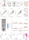
Proteomics of HeLa-MuV, related to Figure 4 (A) Density plot representing the distribution of MS1 intensity of the MuV and human proteomes in non-stressed HeLa-MuV cells. (B) Heatmap representation of the relative fold change (FC) of all MuV proteins inside persistently infected cells at indicated time points of 1 mM As(V), 0.5 mM As(III), or 30 μM As(III) stress, or heat shock (HS) stress at 43°C, in comparison with the non-stress control (n = 3). Asterisks indicate proteins with |log2(fold change)| > 0.5 and adjusted p value < 0.01 (Benjamini-Hochberg method). (C) Relative fold change of P along 30 μM As(III) stress time course relative to control: unmodified protein (solid line) and phosphopeptides (dashed lines). Lines and shaded areas are mean and SEM (n = 3). See also Figure 4A. (D) Scatter plots representing the solubility of viral and host proteins in non-stress control cells (x axis) and under the indicated stress condition (y axis). Solubility is defined by NP40/SDS ratio, indicating the proportion of soluble protein in the lysate pelleting assay. Purple dots: viral proteins; green dots: host factors that exhibited significant change in solubility; gray dots: host factors that did not exhibit significant change in solubility. Proteins with |log2(fold change)| > 0.5 and adjusted p value (Benjamini-Hochberg method) < 0.1 were considered significantly changed. Data are mean values (n = 2). (E) Mean solubility profiles (line) and SEM (shaded area; n = 2) of all MuV proteins along 30 μM As(III) mild stress time course, or after acute heat-shock stress, related to Figure 4B. (F) Representative negative-staining transmission electron microscopy (TEM) images of fractions from sucrose gradient fractionation experiments for isolating nucleocapsids from the 13,000 g pellet of the HeLa-MuV cell after ∼1 h of 0.5 mM As(III) stress to the cells. (G) Heatmap representation of relative fold change (in log2 scale) of all MuV proteins in 13,000 g pellet (input of sucrose gradient fractionation) after 6 h of 1 mM As(V) stress in comparison with the non-stress control, used for normalization of data in (H). Median values are shown (n = 3). (H) Hierarchical clustering of sucrose gradient fractionation profiles (median relative fold change compared with fraction 10, n = 3) of all proteins in non-stress control and 6 h of 1 mM As(V) stress. Thick lines: MuV proteins; thin lines: HeLa proteins. See also Figures 4D and 4E. (I) Fold change of viral proteins in anti-EGFP-P pull-down from cells transfected with P_WT at 6 h of 1 mM As(V) stress compared with non-stress control, quantified by MS (n = 2). Statistical significance of change evaluated as in (D). (J) Comparison of the amount of viral proteins in anti-EGFP-P pull-down between P_deficient and P_WT at non-stress condition, quantified by MS (n = 3). Statistical significance of change evaluated as in (D). (K) Heatmap representation of relative fold change of proteins from the type I interferon signaling pathway (HeLa-MuV cells) shows significant down-regulation along the stress time course compared with the non-stress control (n = 3). Asterisks indicate proteins with |log2(fold change)| > 0.5 and adjusted p value < 0.01 (Benjamini-Hochberg method).
Figure 4
Figure 4
Stress alters protein interaction networks within viral factories (A) Mean relative abundance of P protein (solid line) and its phosphopeptides (dashed line) in HeLa-MuV cells along the stress course in comparison with 0 h control in log2 scale. Shaded areas represent SEM (n = 3). (B) Mean solubility profiles (line) and SEM (shaded area; n = 2) of all MuV proteins in HeLa-MuV cells along the stress course. (C) Structural model of the P-L interface generated with AlphaFold2 (AF2). Left: AF2 predicted model of PIV5 P-L fitted into the cryo-EM map (EMD: 21095) positions the P-IDR at the previously unassigned density (framed; the region corresponding to the MuV-P phosphopeptide in A is indicated with red arrow). Schematic model of N is shown to indicate the context of P-L complex, with a short helix (MoRE) at the C-terminal IDR of N predicted to interact with the P-XD. Right: The zoom-in view of the MuV P-L interface (top) is shown with L in surface charge representation and P in cartoon. Surface charge comparison of the same interface on P-WT versus a mimic of phosphorylated P (S|T mutated to D|E; P_DDED) is shown below. (D) Mean relative abundance of N, P, and L proteins (line) in sucrose gradient fractions, with respect to fraction 10 at stress condition. Apex of co-eluting proteins N, P, and L is observed at fraction 14. Shaded areas: SEM (n = 3). (E) Relative abundance of N, P, and L at the apex of stress condition compared to non-stress control (n = 3). (F) Fold change of N, P, and L in anti-EGFP-P pull-down from cells transfected with P_WT at 6 h of 1 mM As(V) stress compared to non-stress control, quantified by MS (n = 2). (G) Fold change of P phosphopeptide enriched in anti-EGFP-P pull-down in (F). (H) Comparison of partitioning of EGFP-tagged P_WT and P_deficient transfected into HeLa-MuV cells. Cyan: VFs immunostained against MuV-N; gray: DNA DAPI staining; red: EGFP-P. MIP images are shown. Each dot in the plot represents one cell. Statistical significance is evaluated using Wilcoxon test. ns, not significant. (I) Comparison of the amount of N, P, and L proteins in anti-EGFP-P pull-down between P_deficient and P_WT at non-stress condition, quantified by MS (n = 3). See also Figure S3.
Figure S4
Figure S4
Workflow of in situ cryo-correlative electron tomography and tomogram analysis, related to Figure 5 (A) 3D cryo-correlative light and electron microscopy (CLEM) workflow targeting unlabeled MuV factories in vicinity of stress granules (SGs). MuV factories were frequently seen in proximity of SGs identified by mCherry-G3BP1 (see also Figures 2A and 2B). HeLa-MuV cells were seeded and cultured on TEM grids in a culture dish. At different time points of stress, grids with cells were plunge-frozen, followed by imaging with a cryo-confocal light microscope (LM). Grid squares with cells showing SG signals (red; indicated with white arrowhead) and optimal fluorescent beads (yellow) distribution in grid map overviews were chosen for imaging in confocal mode. Lamellae were then prepared by cryo-FIB (focused ion beam) milling at SG locations, using the fluorescent beads as fiducials for 3D correlation between LM and scanning electron microscopy (SEM)/FIB images. Correlating SEM/FIB images with 3D LM signals after lamella preparation confirmed SG location preservation (red signal) in lamella. Overlaying the SEM image with transformed fluorescent signal onto the cryo-TEM image of the lamella allowed identification of SG location and informed tilt series acquisition (indicated by frame) at nearby regions where filamentous structures were seen and later identified to be MuV nucleocapsids. Nu: nucleus. Asterisk: ice contaminants introduced during transfers between the cryo-microscopes. (B) A 6.74 nm-thick tomographic slice of nucleocapsids aligned near the plasma membrane. Cyan arrowheads: nucleocapsids. (C) Representative tomographic slice showing MuV factories at 1 mM As(V) stress. Cyan arrowheads: nucleocapsids (both top and side views, two of each); yellow arrowheads: ribosomes. Slice thickness: 6.52 nm. See also Figure 5C. (D) Examples of persistence length measurement (left) and histogram of nucleocapsid length (right) derived from tracing of all nucleocapsids in two tomograms representing curved and straight nucleocapsids, obtained at indicated stress conditions. 3D coordinates along all traced nucleocapsids within one tomogram were used to calculate the “tangent-correlation length” (apparent persistence length in the filament ensemble), which is inversely related to the curvature of filament (see also STAR Methods). Mean length of filaments per tomogram was determined to define the length range used for fitting. See also Figure 5D for quantification of nucleocapsid persistence length measurements in all tomograms generated in this study.
Figure 5
Figure 5
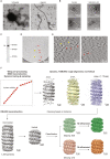
MuV viral factories and nucleocapsids undergo structural changes during stress (A and B) 6.74-nm-thick tomographic slice of a VF and the corresponding 3D segmentation. Exemplary nucleocapsids are indicated with cyan arrowheads (top and side views, two of each) in (A) and colored the same in (B). Inset: enlarged view. Red arrowheads indicate flexible densities extending from nucleocapsids. LD, lipid droplet; Mito, mitochondrion; ER, endoplasmic reticulum; Ribo, ribosome; V, vesicle. (C) Representative tomographic slices (thickness left to right: 6.74, 6.52, and 6.52 nm) of nucleocapsids (cyan arrowheads) and associated flexible densities (red arrowheads in insets) in VFs at indicated control and stress conditions. (D) Volume fractions and apparent persistence lengths of nucleocapsids in tomograms at indicated control and stress conditions. See also Figure S4 and Videos S1, S2, and S3.
Figure S5
Figure S5
Structure determination of extracted MuV nucleocapsids, related to Figure 6 (A) Negative-staining TEM of nucleocapsids enriched in the 13,000 g pellet from cell lysates (left), and the effect of heparin addition on nucleocapsid morphology. The cells were stressed with 0.5 mM As(III) for 1 h. The heparin-straightened nucleocapsid sample was used for data acquisition and structural analysis in Figures 6 and S5D–S5F. (B) Negative-staining TEM of nucleocapsids enriched in the 13,000 g pellet from lysates of cells at the non-stress control or 6 h of 1 mM As(V) stress. (C) Western blot detects full-length MuV-N in the 13,000 g pellet from lysate of cells after 1 h of 0.5 mM As(III) stress. (D) Representative cryo-TEM image of extracted nucleocapsids (13,000 g pellet, red arrowheads) at intermediate magnification. Nearby ribosomes are labeled (yellow arrowheads). (E) Two 3.39 nm-thick tomographic slices of the nucleocapsid in (D), 12 nm apart in the z direction. Red arrowheads: straight segments of a long nucleocapsid used for structural analyses; yellow arrowheads: ribosomes. (F) Subtomogram averaging workflow for the extracted nucleocapsids from HeLa-MuV cells after ∼1 h of 0.5 mM As(III) stress. Frames in each tilt (20 tilt series in total) were aligned, averaged, and CTF-estimated in Warp (CTF, contrast transfer function). Averaged tilt series images were aligned and reconstructed into tomograms in IMOD. Alignments were imported into Warp for 3D-CTF estimation, tomogram reconstruction and application of a deconvolution filter. Nucleocapsids were traced manually in Dynamo. 1,209 center positions along the nucleocapsids were used to crop subtomograms with orientations assigned based on filament directions, with 30° in-plane rotation initially assigned to subsequent subtomograms. Template-free alignment was done in Dynamo at 4 times binning. Alignment results and average were used for subsequent processing of 2 times binned and unbinned subtomograms in TOM/AV3. No helical symmetry was applied at these stages. 3D refinement in RELION was first performed without applying symmetry until helical parameters could be determined in RELION. Helical reconstruction and classification were then done to separate subtomograms of different helical parameters. M refinement with symmetry expansion subsequently improved resolution and map quality. Except for the Dynamo alignment step, CTF-corrected subtomograms and 3D CTF models were all reconstructed in Warp. Overlapping particles were removed in intermediate steps and particle numbers used in each step are indicated. Also see STAR Methods.
Figure 6
Figure 6
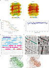
Structures of isolated MuV nucleocapsids reveal two packing modes with variable surface accessibility of RNA and C-terminal IDRs (A) Two classes of subtomogram averages of extracted nucleocapsids resolved to 4.5 Å (majority class) and 6.3 Å (minority class). Four subunits of each average are segmented to illustrate their different packing. RNA densities are colored in yellow. Zoomed-in views illustrate the quality of the map and fitted models. (B and C) Cartoon representation of the atomic model of MuV-N (amino acids 3–405) with RNA for four subunits of the majority class. (D) Subunit packing (colored as in B) between neighboring turns (upper panel) and within the same turn (lower panel). Circles: packing interfaces. (E) Lumen view comparison of the two classes in (A). CTD arms of neighboring subunits (green, circled) are not resolved in the minority class (orange). Dotted arrowheads: NTD-arms resolved in both maps. (F) Surface view comparison of the two classes (colored as in B). Key residues potentially responsible for RNA binding are labeled (red asterisks, listed on the left). Arrow in the orange frame indicates a shift of the upper subunit toward the lower turn RNA binding pocket in the minority class. Dotted circles indicate unoccupied space in the majority class (left) that becomes occupied in the minority class (right), which blocks access of the C terminus (arrowheads) to the nucleocapsid surface. See also Figures S5 and S6.
Figure S6
Figure S6
Structural analysis of the two classes in extracted nucleocapsids, related to Figure 6 (A) Local resolution maps for the majority and minority class averages. (B) Fourier shell correlation (FSC) plots calculated between the two independently refined half-sets for the majority and minority maps shown in (A). Global resolution is provided at the 0.143 criterion. (C) Plot of per residue cross correlation (CC) coefficients between the generated atomic model for N (amino acid 3–405) and the segmented subunit in the majority class map. Dotted line: average CC value of 0.80. (D) Illustration of the secondary structure of N. Secondary structure of the C-ter IDR was predicted with PSIPRED. (E) Mapping of two classes into tomograms. Red arrowheads indicate minority class mapped regions, showing densities in the nucleocapsid lumen, possibly representing the C-ter IDR of N protein in this conformation. (F) Rigid body fitting of the models generated in this study to the cryo-EM maps of helix-dense (EMD: 31368, green, similar to our majority class) and helix-hyper (EMD: 31369, orange, similar to our minority class) of the in vitro reconstituted nucleocapsids reported by Shan et al. The critical CTD-arm region (encircled, helices 16 and 17) is only resolved in one class (helix-dense by Shan et al., similar to our majority class), while it is missing in the other class in line with our results.
Figure S7
Figure S7
Subtomogram averaging for nucleocapsids in situ, related to Figure 7 (A) Subtomogram averaging workflow for curved nucleocapsids inside HeLa-MuV cells at 1 h of 0.5 mM As(III) stress, the same condition used for structure determination of isolated nucleocapsids. Nucleocapsids were traced by filament tracing in Amira and sampled with custom-made MATLAB scripts. An over-sampling strategy for particles at the nucleocapsid surface was used because the filaments are too curved to generate moderate or high resolution maps and to be averaged by helical reconstruction. After initial alignment in TOM/AV3, RELION classification resulted in three classes with mixed helical rises. The connecting densities between turns in back view (luminal, arrows) show high heterogeneity within each average, leading to difficulty in determination of exact helical parameters. Also see STAR Methods. (B) FSC plots for the class averages in (A), with the 0.143 criterion. (C) Map comparison between class averages in (A). The dotted lines qualitatively represent the different inclination of the helical turns in the compared classes. (D) Subtomogram averaging workflow for the straight nucleocapsids inside HeLa-MuV cells at 6 h of 30 μM As(III) mild stress and 1 mM As(V) acute stress. Particles from 6 tomograms at the two prolonged stress conditions were merged. Averaged tilt series images were CTF-estimated and reconstructed into tomograms in Warp with alignment files from IMOD, and denoised in Warp. Nucleocapsids were traced by filament tracing in Amira and sampled along the central lines with custom-made MATLAB scripts. Initial orientations of subtomograms were assigned based on filament directions with 30° in-plane rotation for subsequent subtomograms. Template-free alignment was done in Dynamo at 8 times binning. Alignment results and average were used for processing of 4 times binned subtomograms in TOM/AV3. No helical symmetry was applied at these stages. 3D refinement in RELION was first done at 2 times binning without applying symmetry, until helical parameters could be determined. Helical reconstruction was then done to improve the resolution. M refinement with helical symmetry subsequently improved the map quality. Helical reconstruction was finally done with unbinned particles. Classification trials resulted in classes with very similar helical parameters, and are not shown here. CTF-corrected subtomograms and 3D CTF models were all reconstructed in Warp. Overlapping particles were removed in intermediate steps, and particle numbers at each step are indicated. See also STAR Methods. (E) FSC plot for the final map shown in (D), with the 0.143 criterion. (F) Local resolution map for the final map shown in (D).
Figure 7
Figure 7
In-cell structure of MuV nucleocapsids at prolonged stress exhibits an RNA accessible state (A) Subtomogram average of the in-cell MuV nucleocapsids resolved to 6.5 Å. RNA densities in yellow. (B) Lumen view of the in-cell MuV nucleocapsid. CTD arms of three neighboring subunits are encircled and the NTD-arms are indicated with dotted triangles, similar to the majority class in Figure 6E. (C) Zoom-in surface view of the in-cell MuV nucleocapsid shows accessible RNA and CTD-arm (indicated with black arrowhead and the surrounding region with dotted circle). Subunits are docked and colored as in Figure 6F. (D and E) Cross-section and surface views of the difference map (purple) between the majority class in Figure 6A (gray) and the in-cell nucleocapsids. Densities in purple are only found in the in-cell map, indicating potential location of the C-terminal IDR at the interface between neighboring subunits. RNA density in yellow. (F) Proposed model for stress-induced activation of viral replication in phase-separated MuV factories. See also Figure S7.

Comment in

References

    1. Virgin H.W., Wherry E.J., Ahmed R. Redefining chronic viral infection. Cell. 2009;138:30–50. doi: 10.1016/j.cell.2009.06.036. - DOI - PubMed
    1. Padgett D.A., Sheridan J.F., Dorne J., Berntson G.G., Candelora J., Glaser R. Social stress and the reactivation of latent herpes simplex virus type 1. Proc. Natl. Acad. Sci. USA. 1998;95:7231–7235. doi: 10.1073/pnas.95.12.7231. - DOI - PMC - PubMed
    1. Piette J., Legrand-Poels S. HIV-1 reactivation after an oxidative stress mediated by different reactive oxygen species. Chem. Biol. Interact. 1994;91:79–89. doi: 10.1016/0009-2797(94)90028-0. - DOI - PubMed
    1. Rubin S., Eckhaus M., Rennick L.J., Bamford C.G., Duprex W.P. Molecular biology, pathogenesis and pathology of mumps virus. J. Pathol. 2015;235:242–252. doi: 10.1002/path.4445. - DOI - PMC - PubMed
    1. Su S.B., Chang H.L., Chen A.K. Current status of mumps virus infection: epidemiology, pathogenesis, and vaccine. Int. J. Environ. Res. Public Health. 2020;17 doi: 10.3390/ijerph17051686. - DOI - PMC - PubMed

Publication types

Substances

LinkOut - more resources