Review
. 2023;6(1):82.
doi: 10.1038/s42005-023-01195-z. Epub 2023 Apr 24.

The Extremely Brilliant Source storage ring of the European Synchrotron Radiation Facility

Affiliations
Review

The Extremely Brilliant Source storage ring of the European Synchrotron Radiation Facility

Pantaleo Raimondi et al. Commun Phys. 2023.

Abstract

The Extremely Brilliant Source (EBS) is the experimental implementation of the novel Hybrid Multi Bend Achromat (HMBA) storage ring magnetic lattice concept, which has been realised at European Synchrotron Radiation Facility. We present its successful commissioning and first operation. We highlight the strengths of the HMBA design and compare them to the previous designs, on which most operational synchrotron X-ray sources are based. We report on the EBS storage ring's significantly improved horizontal electron beam emittance and other key beam parameters. EBS extends the reach of synchrotron X-ray science confirming the HMBA concept for future facility upgrades and new constructions.

Keywords: Techniques and instrumentation.


Conflict of interest statement

Competing interestsThe authors declare no competing interests.

Figures

Fig. 1
Fig. 1. Lattice functions and magnet layout for the hybrid multi-bend Achromat SR standard cell.
The Dipoles, quadrupoles, sextupoles, multipoles and diagnostic elements along the cell (position s) are shown as violet, pink, light green, dark green and black objects respectively. The βx, βz, and ηx parameters are shown as blue, red and orange lines respectively. Reproduced by permission.
Fig. 2
Fig. 2. Brilliance curves.
The figure shows the brilliance curves for the former ESRF lattice (red), for the EBS lattice (blue) and for a future EBS upgrade with “mini-β” sections and ultra-short-period undulators (green). The dashed curves are for ex-vacuum undulators: 88 mm period, 4 m long circular polarisation undulator at low-energy, 35 mm period, 4.8 m long planar undulator at medium energy, and 20 mm period, 4.8 m long planar undulator at 14 keV. The solid curves are for 2 m long cryogenic permanent magnet undulators (CPMUs) with 14.4 mm period for the ESRF DBA and ESRF EBS, and 12 mm (still to be built and demonstrated) for future mini-β upgrades. The brilliance curves were computed with the SRW software, taking into account the energy spread and detuning,.
Fig. 3
Fig. 3. Main milestones of the ESRF-EBS machine commissioning.
The figure shows the main milestones for the EBS commissioning from November 2019 when commissioning started, until May 2019 when beam was given for first user activities.
Fig. 4
Fig. 4. Undulator harmonics.
The figure shows the 8th to 14th undulator harmonics from a 1.6 m long, U35 undulator (35 mm period) with the gap set at 12.6 mm. The inset shows a high-resolution scan of the 9th harmonic with the gap set at 13.4 mm.
Fig. 5
Fig. 5. Photon flux at beamline ID10.
The curves are for flux from a single 1.6 m long, 27 mm period undulator measured with a 0.15 × 0.15 mm2 slit at 27.2 m from the source (Measurement: black line). The undulator deflection parameter was set to 1.2, corresponding to the peak brilliance. For the simulations, the rms electron beam size was kept fixed while the electron beam divergence was set to ±50% of the nominal value (red full line, red dotted (Horizontal divergence/1.5) and red dashed (Horizontal divergence × 1.5) lines).
Fig. 6
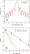
Fig. 6. Fraunhofer diffraction patterns.
a Fraunhofer diffraction from a single pair of slits with opening 25 × 25 μm2, measured (Measurement, black line) and calculated (Simulation, red line) at beamline ID10. Primary slits: 0.2 × 0.2 mm2 at 27 m, asymmetrical slits at 60 m and detector at 7.8 m from the slits, photon energy: 7.24 keV, detector slits 5 × 5 μm2. The pattern is normalised to the peak value. b Fringe visibility of Fraunhofer diffraction patterns as a function of the horizontal slits’ width (markers: measurements, lines: fit). The horizontal coherence length ξH at 60 m was estimated with V=exp(a2/2ξH2) were a is the slit aperture. The estimates for the horizontal coherence length from a Gauss-Schell model are ξH=53.4 μm at 7.24 keV and ξH=19.1 μm at 20.95 keV. The error bars are given by the he standard deviation of the visibility values for each slits setting.
Fig. 7
Fig. 7. Undulator beam images.
Monochromatic beam images of a 1.6 m long, U35 undulator source (35 mm period) with deflection parameter K = 2.293, recorded on beamline ID15A at 40.4 keV (15th harmonic), 69.9 keV (26th harmonic) and 99.5 keV (37th harmonic). The images were recorded at a distance of 65 m with a PCO-edge camera coupled to a 2× optics and a LuAG:Ce scintillator. The image pixel size is 3.18 μm pixel. The central disks are the main harmonics (e.g., the 15th harmonic at 40 keV) and the rings are higher-order harmonics (e.g., the 16th harmonic at 40 keV).
Fig. 8
Fig. 8. Photon flux from the 1.5 m long CPMU at beamline ID15A.
The flux was measured for a 18 mm period with 0.97 T peak field at 6 mm gap, through a pair of slits set at 0.2 × 0.2 mm2 at 30 m distance. The plus signs represent measurements after optimising the monochromator energy for each undulator gap value. The disks are calculations for an ideal undulator (undulator harmonics 5–11). The horizontal emittance of the storage ring was 160 pm rad.

References

    1. The Nobel Prize in Physics 2021. https://www.nobelprize.org/ Nobel Prize Outreach AB 2022 (2022).
    1. Jaeschke, E. Synchrotron light sources and free-electron lasers: accelerator physics, instrumentation and science applications (Springer, Cham, 2020).
    1. Chasman R, Green GK, Rowe EM. Preliminary design of a dedicated synchrotron radiation facility. IEEE Trans. Nucl. Sci. 1975;22:1765–1767. doi: 10.1109/TNS.1975.4327987. - DOI
    1. Encyclopedia of Synchrotron Radiation Facilities, RIKEN Spring-8 Center (2020).
    1. Einfeld D, Schaper J, Plesko M. Design of a diffraction limited light source (DIFL) Proc. Part. Accelerator Conf. 1995;1:177–179. doi: 10.1109/PAC.1995.504602. - DOI