Review
. 2023 Apr 23;23(9):4227.
doi: 10.3390/s23094227.

Metamaterials for Acoustic Noise Filtering and Energy Harvesting

Affiliations
Review

Metamaterials for Acoustic Noise Filtering and Energy Harvesting

Fariha Mir et al. Sensors (Basel). .

Abstract

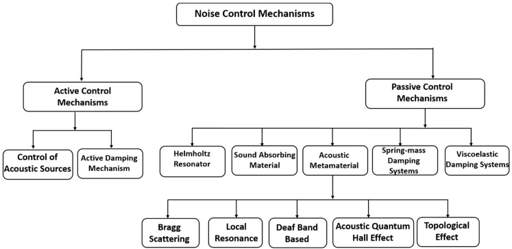
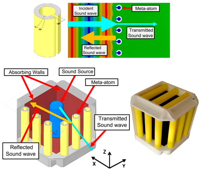
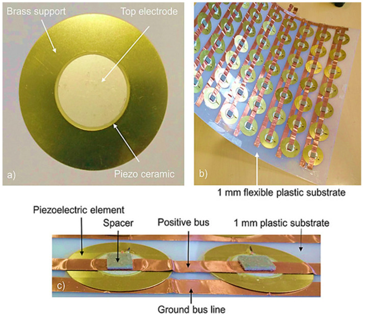
Artificial methods for noise filtering are required for the twenty-first century's Factory vision 4.0. From various perspectives of physics, noise filtering capabilities could be addressed in multiple ways. In this article, the physics of noise control is first dissected into active and passive control mechanisms and then further different physics are categorized to visualize their respective physics, mechanism, and target of their respective applications. Beyond traditional passive approaches, the comparatively modern concept for sound isolation and acoustic noise filtering is based on artificial metamaterials. These new materials demonstrate unique interaction with acoustic wave propagation exploiting different physics, which is emphasized in this article. A few multi-functional metamaterials were reported to harvest energy while filtering the ambient noise simultaneously. It was found to be extremely useful for next-generation noise applications where simultaneously, green energy could be generated from the energy which is otherwise lost. In this article, both these concepts are brought under one umbrella to evaluate the applicability of the respective methods. An attempt has been made to create groundbreaking transformative and collaborative possibilities. Controlling of acoustic sources and active damping mechanisms are reported under an active mechanism. Whereas Helmholtz resonator, sound absorbing, spring-mass damping, and vibration absorbing approaches together with metamaterial approaches are reported under a passive mechanism. The possible application of metamaterials with ventilation while performing noise filtering is reported to be implemented for future Smart Cities.

Keywords: acoustic metamaterials; acoustic noise barriers; air ventilation; energy harvesting; metamaterials; noise barriers; piezoelectric; piezoelectric energy harvesting; sound insulation; topological acoustics.


Conflict of interest statement

The authors declare no conflict of interest.

Figures

Figure 1
Figure 1
Comparison of noise level with daily life examples.
Figure 2
Figure 2
Classification of noise control mechanism.
Figure 3
Figure 3
Schematic illustration of the cochlear-inspired structure. (a) Front view of Helmholtz resonator unit cell. (b) Cross-sectional view of the Helmholtz resonator unit cell showing the hollow interior of the cylinder and spiral tube. (c) Archimedean spiral and (d) isometric view of the entire structure [38].
Figure 4
Figure 4
(a) Schematic illustration of the proposed planar acoustic filter. (b) Photographs of the fabricated filters [39].
Figure 5
Figure 5
Sound-absorbing materials developed by various researchers. (a) Ultrathin coiling-based metamaterial panel [48]; (b) 3D multi-resonant sound absorbing metamaterial: (b.1) Quarter-wavelength, (b.2) Helmholtz resonator, (b.3) Three dimensional unit cell for eigenvalue problems, (b.4) Scattering problem for the calculation of the IL of an infinite LRSC slab [49]; (c) 1D metastructure with double negative parameters: (c.1) schematics of the unit cell, (c.2) Dimensions of the cell (c.3) Photograph of the fabricated metastructure (c.4) Top view of the metastructure without membrane [50]; (d) Ultrathin acoustic metasurface-based Schroeder diffuser (d.1) 1D Schroeder diffuser, (d.2) 2D Schroeder diffuser (d.3) proposed metasurface based Schroeder diffuser [51]; (e) ultrathin metastructure with (e.1) thin perforated plate with holes is placed on top of (e.2) a rigid squared air cavity with a coiled chamber [52]; (f) Acoustic perfect absorbers via spiral metasurface with embedded apertures [53].
Figure 6
Figure 6
Bragg scattering phenomena observed in various acoustic metamaterial structures. (a) Tunable acoustic metamaterial with (a.1) square array of circular holes and resonators (a.2) geometry of (a.1) can be recognized by instability subjected to equibiaxial compression (a.3) primitive RVE in undeformed configuration, (a.4) enlarged RVE in deformed configuration [56]; (b) Triply periodic co-continuous acoustic metamaterial capable of filtering waves using the Bragg scattering phenomenon (b.1) 2 × 2 × 2 unit cells with simple cubic lattice, body centered cubic lattice, face centered cubic lattice, face centered cubic lattice and octet-truss lattice, (b.2) corresponding phase A in these metamaterials, (b.3) corresponding phase B in these metamaterials [57]; (c) Piezoelectric resonator arrays for tunable acoustic waveguides and metamaterials (c.1) schematic diagram of the phononic crystal plate with cylindrical stubs and L shape waveguide, (c.2) schematic diagram of the unit cell of the vertical channel [58].
Figure 7
Figure 7
Local resonance phenomena observed in various structures. (a) Locally resonant metamaterial: (a.1) Optimal design cross section of the metamaterial and corresponding unit cell, (a.2) first Brillouin zone (square) and irreducible Brillouin zone (triangle) for a square lattice; [62]; (b) Elastic wave propagation in thin wave metamaterial [65]; (c) Design demonstration of MetaWall noise barrier (c.1) entire brick, (c.2) unit cell [66]; (d) Energy harvesting using sub-wavelength scale acousto-elastic metamaterial [67].
Figure 8
Figure 8
(1) (a) B, deaf, and T band mode shapes of the PVC cylinder surrounded by the air pressure mode shapes with arrows, (b) band structure before tuning, identified near region A, (c) numerical calculation of the transmit showing almost zero transmission near deaf band; (2) Accidental degeneracy for region A and B: (a) Unit cell for region A with PnCs of radius r = 0.212a in air matrix (b) Dispersion relation for region A (c) magnified view of the Dirac like point for region A, (d) Unit cell for region B with PnCs of radius r = 0.1408a in air matrix, (e) dispersion relation after decreasing the radius, (f) magnified view of the Dirac like point for region B [71].
Figure 9
Figure 9
Synthesized acoustic magnetic field and relativistic Landau quantization for observing acoustic quantum Hall effect (a) simulated Dirac point shifts in momentum space, (b) Landau gauge potential sonic crystal with a linearly varying ξ along y direction and a transitional invariance along x direction, (c) spectrum near the Dirac frequency, (d)pressure amplitude distribution for three eigenstates labeled in (c) [72].
Figure 10
Figure 10
(1) Fabrication steps of soft MAM (a) reference configuration, (b) Initial configuration, (c) spraying particles and applying voltage, (d) side view of the cell (e) 3D view of the unit cell. (2) The band structure and the Dirac cone in soft MAM [73].
Figure 11
Figure 11
Visualization of (a) Bidisperse honeycomb lattice, (b) breathing Kagome lattice of soda cans. (c) Dispersion relation of the breathing Kagome lattice of cans and (dg) acoustic field map of the crystalline mode at the valley K and K’ [74].
Figure 12
Figure 12
(a) Band structures of the honeycomb phononic crystals for the ordinary state (left), double Dirac cone (middle), and topological state (right). (b) Pressure fields for the ordinary (left panel) and topological (right panel) states [78].
Figure 13
Figure 13
(a) Tight-binding model for the kagome lattice; (b) Unit cell of the acoustic kagome lattice, with a cylindrical resonator at each site joined by thin waveguides; (c) Topological mode shape; (d) Numerically computed bulk bands for the acoustic kagome lattice [79].
Figure 14
Figure 14
(A) Schematic and (B) realistic design of the Wigner-Seitz unit cell of the expanded pyrochlore lattice (C) first Brillouin zone of the FCC lattice (D) photograph of the 3D topological metamaterial assembled from 3D printed metamolecules, with boundary cells attached [80].
Figure 15
Figure 15
Spring-mass damping systems to suppress noise. (a) Acoustic metamaterial plate with elastic wave absorption [81]; (b) Structural vibration suppression in laminate acoustic metamaterial [82].
Figure 16
Figure 16
Vibration absorbing structure (a) viscoelastic damping for mid-frequency noise control [88], (b) vibration reduction of an existing glass window [89], (c) noise reduction passive control system based on viscoelastic material-based retrofit [90].
Figure 17
Figure 17
Diffraction resonators or acoustic cells. Diameters of the air holes: 20 mm for (a1a3), and 50 mm for (b1b3). There are three structures: one room for (a1,b1), two rooms for (a2,b2), and four rooms for (a3,b3) [92].
Figure 18
Figure 18
Acoustic metamaterials with ventilation for fluid flow. (a) Broadband acoustic absorber with ventilation performance [95], (b) omnidirectional ventilated acoustic barrier [96], (c) high efficiency ventilated metamaterial at low frequency [93], (d) acoustic metamaterial for fluid passage and soundproofing [98], (e) acoustic metacages with steady air flow [94], and (f) ultra open metamaterial silencer [97].
Figure 19
Figure 19
Acoustic metamaterials with ventilation for airflow and noise reduction using (a) double-facade system with a plot of measured sound reduction index (Rm) of the experimental wall (i: one layer fully closed and one fully open; ii: both layers fully closed) [99], (b.1) Photographs of the measurement set-up of the installed glazed surface (1–6) and (b.2) the absorptive material (polyurethane conglomerate) used with the louvers [100], (c) zig-zag staggered window configuration [101], and (d) sonic crystals-based window system and the plots having different settings and the measured insertion loss spectra under traffic noise an [102].
Figure 20
Figure 20
Helmholtz resonators-based acoustic metamaterials with ventilation for airflow and noise reduction using (a) HR-based transparent window panel [92], (b) HR-based ventilated metamaterial unit cell composed of two necks and a single chamber [103], (c) HR-based perforated and constrained acoustic metamaterial [104].
Figure 21
Figure 21
Acoustic metacage with ventilation for airflow and noise reduction having C-shaped meta-atoms and metacage capsule [105].
Figure 22
Figure 22
Acoustic meta-absorbers with ventilation for airflow and noise reduction using (a) dual resonators-based cell unit [106] and (b) hexagonal orchestrated six labyrinthine type unit cells [107].
Figure 23
Figure 23
Coiled-up space acoustic metamaterial structure having a central orifice for air ventilation and a coiled-up helical pathway for noise reduction [108].
Figure 24
Figure 24
Classification of piezoelectric energy harvesting sources.
Figure 25
Figure 25
(a) Structure of the energy-harvesting tile active layer using commercially available piezoelectric materials (b) matrix of 8X7 elements on flexible substrate (c) structural detail of the arrays. [109].
Figure 26
Figure 26
Mechanism of a galloping energy harvester [116].
Figure 27
Figure 27
U-VPEH model design proposed by Sun et al. [121].
Figure 28
Figure 28
Buckled beam structure for vibration-based energy harvesting (a) schematic diagram of piezoelectric buckled bridge, (b) cross-section of the steel support and piezoelectric layer (c) electrical circuit of the system [128].
Figure 29
Figure 29
Sound energy harvesting mechanism [129].
Figure 30
Figure 30
Acoustic energy harvesting structures. (a) Membrane-type sound absorber and energy harvester [130], (b) compact energy harvester with beam-based PZT [131], (c) planar acoustic metamaterial [132], (d) energy harvester using a metallic substrate and a proof mass [133], (e) 3D printed helix structure with PZT patch [134], (f) low-frequency acoustic energy harvester based on planar Helmholtz resonator [135], (g) acoustic energy harvesting using coupled sonic crystal and Helmholtz resonator: (g.1) structure diagram of the Sonic crystal resonator structure, (g.2) structure diagram of the electromechanical Helmholtz resonator structure, (g.3) structural diagram of the coupled resonance structure, (g.4) photograph of the coupled resonance structure [136].
Figure 31
Figure 31
Spiral Helmholtz resonator-type acoustic energy harvester (a) entire block, (b) top view of the resonator block, numbers 1–7 representing the multiple Helmholtz resonators used inside the block with varying diameter, (c) side view of a single Helmholtz resonator [137].
Figure 32
Figure 32
Selection criteria of the best noise barrier.

References

    1. Elliott S. Vehicle Noise and Vibration Refinement. Elsevier; Amsterdam, The Netherlands: 2010. Active noise and vibration control in vehicles; pp. 235–251.
    1. Tichy J. Current and future issues of active noise control. J. Acoust. Soc. Jpn. E. 1991;12:255–262. doi: 10.1250/ast.12.255. - DOI
    1. Silcox R.J., Lester H., Abler S. An evaluation of active noise control in a cylindrical shell. J. Vib. Acoust. 1989;111:337–342. doi: 10.1115/1.3269862. - DOI
    1. Dorling C., Eatwell G., Hutchins S., Ross C., Sutcliffe S. A demonstration of active noise reduction in an aircraft cabin. J. Sound Vib. 1989;128:358–360. doi: 10.1016/0022-460X(89)90779-7. - DOI
    1. Elliott S., Nelson P., Stothers I., Boucher C. Preliminary results of in-flight experiments on the active control of propeller-induced cabin noise. J. Sound Vib. 1989;128:355–357. doi: 10.1016/0022-460X(89)90778-5. - DOI

LinkOut - more resources