. 2023 Apr 29:31:100497.
doi: 10.1016/j.pacs.2023.100497. eCollection 2023 Jun.

Surface-plasmon-enhanced strain-wave-induced optical diffraction changes from a segmented grating

Affiliations

Surface-plasmon-enhanced strain-wave-induced optical diffraction changes from a segmented grating

Thomas J van den Hooven et al. Photoacoustics. .

Abstract

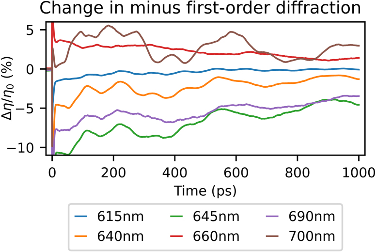
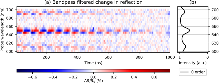
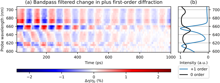
We report on surface-plasmon-polariton-enhanced (SPP-enhanced), strain-wave-induced reflection and diffraction changes on a Au-covered, segmented grating. The segmented grating has a 6020 nm period, and its lines are segmented into 7 periods of a 430 nm period grating, which allows the excitation of SPPs. This grating has three SPP resonances at different optical wavelengths, for the same incident angle. Pump-pulse-induced strain waves are probed by measuring reflection and diffraction of a tunable probe pulse in a wavelength range that includes all three SPP resonances. Surface Acoustic Waves (SAWs) and Longitudinal Waves (LWs) are identified. When probing close to SPP resonances, the reflection changes from SAWs and LWs are strongly enhanced by factors of 23 and 36, respectively, compared with reflection changes observed when probing at off-resonance wavelengths. The relative SAW- and LW-induced diffraction changes are larger by additional factors of up to 3.3 and 2.6, respectively, compared to the reflection changes.

Keywords: Diffraction; Nanostructures; Photoacoustics; Segmented grating; Surface plasmon polaritons; Ultrafast.


Conflict of interest statement

The authors declare that they have no known competing financial interests or personal relationships that could have appeared to influence the work reported in this paper.

Figures

Fig. 1
Fig. 1
(a) A schematic view of the experimental setup with the used wavelengths, indicated by the differently coloured beams, OPA: Optical Parametric Amplifier, BBO: β-barium borate crystal. (b) AFM-micrograph of the Au-covered segmented grating used in the experiments. (For interpretation of the references to colour in this figure legend, the reader is referred to the web version of this article.)
Fig. 2
Fig. 2
Measured and calculated spectra of the specular reflection, plus and minus, first- and second-order diffraction. (a) Measured (solid) and calculated (dashed) ratio of the reflection spectra of p and s-polarised incident light. (b and c) Measured (solid) and calculated (dashed) individually normalised spectra of plus (red) and minus (blue), first-(b), and second-order (c) diffraction, for p-polarised incident light. (For interpretation of the references to colour in this figure legend, the reader is referred to the web version of this article.)
Fig. 3
Fig. 3
Sketch of the coupling of SPPs to free space light modes, which propagate in a direction with an angle θout with the z-axis and with wavevector k0 using a sub-wavelength grating with angular spatial frequency kg.
Fig. 4
Fig. 4
Measured probe-pulse reflection changes as function of time delay between the pump and probe pulse after excitation by the 400 nm central wavelength pump pulse, for selected probe wavelengths. Indicated with red arrows is the change in sign when measuring with a wavelength just below an SPP resonance, at 645 nm (orange curve), compared to measuring at the SPP resonance, at 650 nm (green curve). Note that sign changes can be seen for other time delays as well. (For interpretation of the references to colour in this figure legend, the reader is referred to the web version of this article.)
Fig. 5
Fig. 5
(a) 2D plot of the measured probe pulse reflection changes as function of time delay between the pump and probe pulse, where the slowly decaying background has been removed, for probe wavelengths between 600 and 700 nm. Indicated with black dashed lines is the increase in SAW period for increasing probe wavelength. (b) Ratio of measured p- and s-polarised reflection spectra. (For interpretation of the references to colour in this figure legend, the reader is referred to the web version of this article.)
Fig. 6
Fig. 6
(a) 2D plot of the FFT spectra of the measured probe pulse reflection changes, for probe wavelengths between 600 and 700 nm. (b) Ratio of measured p- and s-polarised reflection spectra. (For interpretation of the references to colour in this figure legend, the reader is referred to the web version of this article.)
Fig. 7
Fig. 7
Measured changes in minus first-order probe diffraction as function of time delay between the pump and probe pulse after excitation by the 400 nm pump pulse, for selected probe wavelengths. (For interpretation of the references to colour in this figure legend, the reader is referred to the web version of this article.)
Fig. 8
Fig. 8
(a) 2D plot of the measured changes in minus first-order diffraction of probe light as function of time delay between pump and probe pulse, where the slowly decaying background is removed, for probe wavelengths between 600 and 705 nm. Indicated with black dashed lines is the increase in SAW period for increasing probe wavelength. (b) The ratio of measured p- and s-polarised reflection spectra and the minus first-order diffraction spectrum. (For interpretation of the references to colour in this figure legend, the reader is referred to the web version of this article.)
Fig. 9
Fig. 9
(a) 2D plot of the FFT of the measured changes in minus first-order diffraction of probe light, for probe wavelengths between 600 and 705 nm. (b) The ratio of measured p- and s-polarised reflection spectra and the minus first-order diffraction spectrum. (For interpretation of the references to colour in this figure legend, the reader is referred to the web version of this article.)
Fig. 10
Fig. 10
(a) 2D plot of the measured changes in plus first-order diffraction of probe light as function of time delay between pump and probe pulse, where the slowly decaying background is removed, for probe wavelengths between 600 and 700 nm. Indicated with black dashed lines is the increase in SAW frequency for increasing probe wavelength. (b) The ratio of measured p- and s-polarised reflection spectra and the plus first-order diffraction spectrum. (For interpretation of the references to colour in this figure legend, the reader is referred to the web version of this article.)
Fig. 11
Fig. 11
Comparison of the measured changes in plus first-order diffraction of probe wavelengths 660 and 670 nm, where the slowly-decaying background is removed, as function of pump–probe delay time. (For interpretation of the references to colour in this figure legend, the reader is referred to the web version of this article.)
Fig. 12
Fig. 12
(a) 2D plot of the FFT of the measured changes in plus first-order diffraction of probe light, for probe wavelengths between 600 and 700 nm. (b) The ratio of measured p- and s-polarised reflection spectra and the plus first-order diffraction spectrum. (For interpretation of the references to colour in this figure legend, the reader is referred to the web version of this article.)
Fig. 13
Fig. 13
(a) 2D plot of the bandpass filtered changes in reflection, as function of time delay between pump and probe pulse, for probe wavelengths between 600 and 700 nm. Cut-on frequency: 8.5 GHz, cut-off frequency: 75 GHz (b) The ratio of measured p- and s-polarised reflection spectra. (For interpretation of the references to colour in this figure legend, the reader is referred to the web version of this article.)
Fig. 14
Fig. 14
(a) 2D plot of the bandpass filtered changes in plus first-order diffraction, as function of time delay between pump and probe pulse, for probe wavelengths between 600 and 700 nm. Cut-on frequency: 8.5 GHz, cut-off frequency: 75 GHz (b) The ratio of measured p- and s-polarised reflection spectra and the plus first-order diffraction spectrum. (For interpretation of the references to colour in this figure legend, the reader is referred to the web version of this article.)
Fig. 15
Fig. 15
Calculated relative reflection and diffraction changes for a 100 pm increase in grating amplitude, as a function of probe wavelength. (For interpretation of the references to colour in this figure legend, the reader is referred to the web version of this article.)
Fig. A.16
Fig. A.16
Example of the unfiltered probe spectrum (red line), with a 687 nm central wavelength, together with six probe spectra, obtained by filtering the original probe spectrum. All curves have been normalised to their maximum. (For interpretation of the references to colour in this figure legend, the reader is referred to the web version of this article.)
Fig. B.17
Fig. B.17
Schematic drawing of the excitation of SPPs by light, incident at an angle θ0 with the z-axis, and with wavevector k0 using a sub-wavelength grating with angular spatial frequency kg. kx is the projection of k¯0 onto the surface.
Fig. C.18
Fig. C.18
Measured time-dependent diffracted signal from an unstructured part of the sample, after excitation by two synchronised 400 nm pulses, creating a transient grating. The measurement diffraction is normalised to the electron peak at 0 ps delay.

References

    1. den Boef A.J. Optical wafer metrology sensors for process-robust CD and overlay control in semiconductor device manufacturing. Surf. Topogr.: Metrol. Prop. 2016;4(2) doi: 10.1088/2051-672x/4/2/023001. Publisher: IOP Publishing. - DOI
    1. Edward S., Zhang H., Setija I., Verrina V., Antoncecchi A., Witte S., Planken P. Detection of hidden gratings through multilayer nanostructures using light and sound. Phys. Rev. Appl. 2020;14(1) doi: 10.1103/PhysRevApplied.14.014015. - DOI
    1. Verrina V., Edward S., Zhang H., Witte S., Planken P.C.M. Photoacoustic detection of low duty cycle gratings through optically opaque layers. Appl. Phys. Lett. 2020;117(5) doi: 10.1063/5.0016078. - DOI
    1. de Haan G., Verrina V., Adam A.J.L., Zhang H., Planken P.C.M. Plasmonic enhancement of photoacoustic-induced reflection changes. Appl. Opt. 2021;60(24):7304. doi: 10.1364/AO.432659. - DOI - PubMed
    1. Yang G., Li J., Wang Y., Ding M., Zhong L. Analytic design of segmented phase grating for optical sensing in high-precision alignment system. Sensors. 2021;21(11):3805. doi: 10.3390/s21113805. - DOI - PMC - PubMed

LinkOut - more resources