. 2023 May 10:6:0144.
doi: 10.34133/research.0144. eCollection 2023.

An Aerial-Wall Robotic Insect That Can Land, Climb, and Take Off from Vertical Surfaces

Affiliations

An Aerial-Wall Robotic Insect That Can Land, Climb, and Take Off from Vertical Surfaces

Qian Li et al. Research (Wash D C). .

Abstract

Insects that can perform flapping-wing flight, climb on a wall, and switch smoothly between the 2 locomotion regimes provide us with excellent biomimetic models. However, very few biomimetic robots can perform complex locomotion tasks that combine the 2 abilities of climbing and flying. Here, we describe an aerial-wall amphibious robot that is self-contained for flying and climbing, and that can seamlessly move between the air and wall. It adopts a flapping/rotor hybrid power layout, which realizes not only efficient and controllable flight in the air but also attachment to, and climbing on, the vertical wall through a synergistic combination of the aerodynamic negative pressure adsorption of the rotor power and a climbing mechanism with bionic adhesion performance. On the basis of the attachment mechanism of insect foot pads, the prepared biomimetic adhesive materials of the robot can be applied to various types of wall surfaces to achieve stable climbing. The longitudinal axis layout design of the rotor dynamics and control strategy realize a unique cross-domain movement during the flying-climbing transition, which has important implications in understanding the takeoff and landing of insects. Moreover, it enables the robot to cross the air-wall boundary in 0.4 s (landing), and cross the wall-air boundary in 0.7 s (taking off). The aerial-wall amphibious robot expands the working space of traditional flying and climbing robots, which can pave the way for future robots that can perform autonomous visual monitoring, human search and rescue, and tracking tasks in complex air-wall environments.


Figures

Fig. 1.
Fig. 1.
The robot landing, climbing, and taking off on a variety of vertical walls. (A) Glass door surface. (B) Wooden door surface. (C) Marble wall surface. (D) Tree surface. (E) Soft spray cloth surface. (F) Lime wall surface. (G) Painted iron sheet surface. The white dotted lines indicate the path of the robot taking off from the ground and flying toward the wall. The cyan dotted lines represent the path of the robot taking off from the wall and moving away or flying toward the ground, and the red dotted lines with arrows indicate the path of the robot climbing on the vertical wall.
Fig. 2.
Fig. 2.
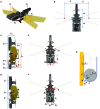
Details of the components and tracking marker positions of the robot. The insect-inspired free-flying robotic platform is controlled through its 2 pairs of independently flapping wings and rotors. (A and B) Description of the robot’s components. (C to E) Wing actuation and aerodynamic forces and torques during pitch control (C), roll control (D), and yaw control (E). Red arrows show the thrust and torques after control actuation. (F to H) Details of the robot design: (F) the climbing mechanism for wall climbing control, (G) the flapping mechanism (of the right wing pair) used for roll torque control, and (H) the rotor adjustment mechanism for yaw torque control. (I) High-speed camera frames capturing the robot during getting closer (i), landing (ii), climbing (iii), taking off (iv), and leaving away from the vertical surfaces (v), from Movie S1.
Fig. 3.
Fig. 3.
Kinematic and dynamic models of the robot. (A) Flight dynamical model. Fh, Ft, Fl, and Fr are the thrust forces generated by the head rotor, tail rotor, left flapping wing, and right flapping wing, respectively. (B) Flight moment arms. d1, d2, l1, and l2 are the geometric distances of the 2 rotors and 2 pairs of flapping wings to the nominal CoM. (C and D) The safety attachment model of the robot on the vertical wall. (C) Model of the flipping action around the contact points between the rear belt and the wall. Here, FNi, i = {(a), (b), (c)} is the support force of the vertical wall on the contact surface of the robot. Fri, i = {(1), (2)}, denotes the negative pressure produced by the head and tail rotors. Fa is the adhesion of the wall to the belt. (D) Integral slipping model. fi, i = {(1), (2)}, denotes the friction on the belts and battery. FN is the total support force of the wall on the robot, and Fr is the total negative pressure from the rotors. (E) Kinematic model of the robot during climbing. The body frame xbCyb is fixed to the robot with the origin at the nominal CoM. VC is the velocity of the robot when climbing upward. (F) Mechanical model of the robot during climbing. Fy is the frictional force of the robot's belt on the wall. Fi, i = {(L), (R)}, is the driving force of the robot. FP is the peeling force of the belt. (G) Process of peeling the adhesive belt from the wall surface. θ is the peeling angle, r is the radius of the wheel, and t is the thickness of the belt. The establishment and description of the kinematic and dynamic equations of the robot when flying and climbing are given in the Supplementary Text.
Fig. 4.
Fig. 4.
Control architecture of the robot. (A) Main electronics and mechanical components of the robot. (B) Control circuit of the robot. The flying–climbing transition control switches the controllers based on the sensor measurements. θd, φd, ψ˙d, ωdClimb, ωdFly, and Md are the desired pitch angle, roll angle, yaw angular rate, climbing throttle, flying throttle, and moment to be tracked, respectively. ni denotes the input signals to the motors, α is the servo deflection angle, ω is the attitude angular rate, and Θ contains a sequence of attitude angles.
Fig. 5.
Fig. 5.
Thrust and attitude torque measurements of the flapping/rotor hybrid power of the aerial–wall robot under various input throttle and roll/pitch/yaw command. (A) Experimental setup for the measurement. The robot was fixed to the sensor. (B) Thrust versus throttle command when only the rotor wings are actuated (i), when only the flapping wings are actuated (ii), and when the combined rotor/flapping wings are actuated (iii). All relationships follow a linear trend (black dashed line) with respective R2 values of 0.993, 0.993, and 0.989 for measurements respectively carried out with 2 rotors, with the flapping mechanism pair, and with the combined rotor/flapping wings, each driven by the ESC. (C) Torque measurements. (i) Roll torque and the corresponding thrust versus roll command. (ii) Pitch torque and the corresponding thrust versus pitch command. (iii) Yaw torque and the corresponding thrust versus yaw command. The solid lines are the average of 5 measurements, and the shaded area around the mean indicates the standard deviations. The gray shaded areas represent the linear region of the average thrust and torque under some interval commands. (D) Measurements of the roll, pitch, and yaw torques performed at 40% throttle command. (i) Roll torque and the corresponding thrust measurements against the roll command for various values of pitch command, color coded according to the legend. (ii) Pitch torque and the corresponding thrust measurements against the pitch command for various values of roll command, color coded according to the legend. (iii) Yaw, roll, pitch torques, and the corresponding thrust measurements against yaw command, color coded according to the legend. The solid lines are the average of 5 measurements, and the shaded area around the mean indicates the standard deviations. The round pie buttons of different colors present the working state of the flapping wing and rotor.
Fig. 6.
Fig. 6.
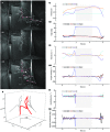
Transitional flight tests of air flight to wall climbing and then to air flight. (A) Composite images of (i) transition from flying to climbing, (ii) climbing, and (iii) transition from climbing to flying. (B) Flight trajectory. (C) Position versus time (i) and body attitude angles versus time (ii). (D) Velocity versus time (i) and body angular rates versus time (ii). (E) Acceleration versus time (i) and body angular accelerations versus time (ii). The solid red lines represent the body of the robot, whose head is indicated by a red dot. The cyan dotted line shows the trend of the robot’s movement. The gray shaded areas represent the corresponding range from completion of the transition from flying to climbing to the end of the climbing phase.

References

    1. Mountcastle AM, Ravi S, Combes SA. Nectar vs. pollen loading affects the tradeoff between flight stability and maneuverability in bumblebees. Proc Natl Acad Sci USA. 2015;112:10527–10532. - PMC - PubMed
    1. Crall JD, Chang JJ, Oppenheimer RL, Combes SA. Foraging in an unsteady world: Bumblebee flight performance in field-realistic turbulence. Interface Focus. 2017;7: Article 20160086. - PMC - PubMed
    1. Ravi S, Kolomenskiy D, Engels T, Schneider K, Wang C, Sesterhenn J, Liu H. Bumblebees minimize control challenges by combining active and passive modes in unsteady winds. Sci Rep. 2016;6:35043. - PMC - PubMed
    1. Karásek M, Muijres FT, Wagter CD, Remes BDW, Croon GCHE. A tailless aerial robotic flapper reveals that flies use torque coupling in rapid banked turns. Science. 2018;361(6407):1089–1094. - PubMed
    1. Woodward MA, Sitti M. Morphological intelligence counters foot slipping in the desert locust and dynamic robots. Proc Natl Acad Sci USA. 2018;115:E8358–E8367. - PMC - PubMed

LinkOut - more resources