Review
. 2023 Sep;12(23):e2300318.
doi: 10.1002/adhm.202300318. Epub 2023 Jun 9.

Biodegradable Piezoelectric Polymers: Recent Advancements in Materials and Applications

Affiliations
Review

Biodegradable Piezoelectric Polymers: Recent Advancements in Materials and Applications

Mohsin Ali et al. Adv Healthc Mater. 2023 Sep.

Abstract

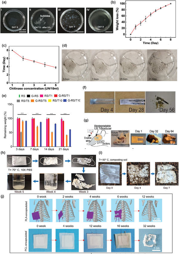
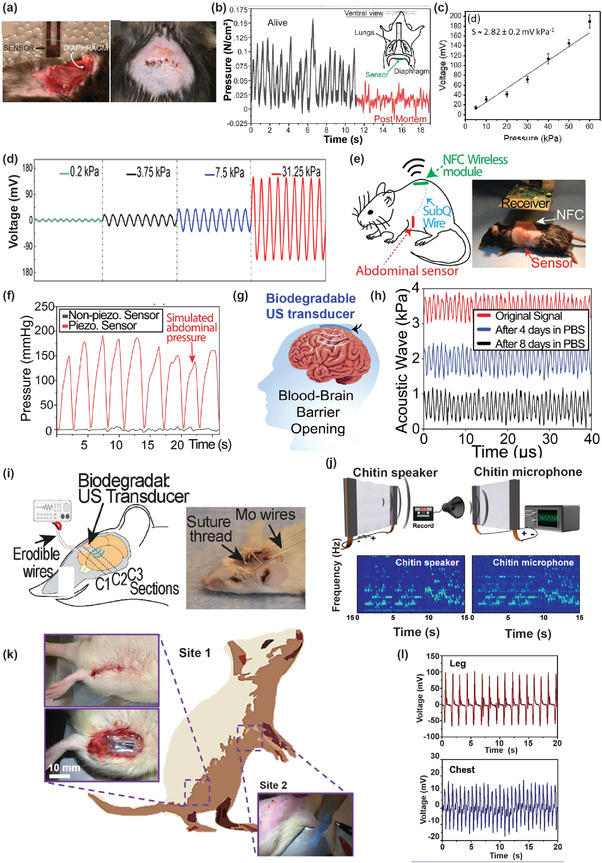
Recent materials, microfabrication, and biotechnology improvements have introduced numerous exciting bioelectronic devices based on piezoelectric materials. There is an intriguing evolution from conventional unrecyclable materials to biodegradable, green, and biocompatible functional materials. As a fundamental electromechanical coupling material in numerous applications, novel piezoelectric materials with a feature of degradability and desired electrical and mechanical properties are being developed for future wearable and implantable bioelectronics. These bioelectronics can be easily integrated with biological systems for applications, including sensing physiological signals, diagnosing medical problems, opening the blood-brain barrier, and stimulating healing or tissue growth. Therefore, the generation of piezoelectricity from natural and synthetic bioresorbable polymers has drawn great attention in the research field. Herein, the significant and recent advancements in biodegradable piezoelectric materials, including natural and synthetic polymers, their principles, advanced applications, and challenges for medical uses, are reviewed thoroughly. The degradation methods of these piezoelectric materials through in vitro and in vivo studies are also investigated. These improvements in biodegradable piezoelectric materials and microsystems could enable new applications in the biomedical field. In the end, potential research opportunities regarding the practical applications are pointed out that might be significant for new materials research.

Keywords: biodegradables; biomedical devices; piezoelectric polymers.


Conflict of interest statement

The authors declare no conflict of interest.

Figures

Figure 1
Figure 1
Advancements in biodegradable piezoelectric biomaterials and emerging applications in the medical field, such as bio‐physiological pressure measurement (abdominal pressure, intraocular pressure, and intracranial pressure), blood‐brain barrier, cell proliferation, human‐machine interface, health monitoring, bone regeneration, and wound healing applications.
Figure 2
Figure 2
Protein and its derivatives‐based devices. a) A completely bent flexible device based on glycine. b) A view of the full‐length flexible device with copper electrodes. Reproduced with permission.[ 64 ] Copyright 2021, Elsevier. c) i) Chitosan/Glycine film peeled off from petri dish. ii) Gold electrode deposited on both sides. iii) Cs/Gly‐based flexible sensor. Reproduced with permission.[ 65 ] Copyright 2020, American Chemical Society. d) Generation of the output voltage by manually compressing the DL‐Alanine film test. Reproduced with permission.[ 47 ] Copyright 2019, American Physical Society. e) Schematic of degradable piezoelectric nanogenerator device based on FF nanorods. Reproduced with permission.[ 84 ] Copyright 2021, Elsevier. f) Schematic representation of piezoelectric nanogenerator (PENG) fabricated by utilizing diphenylalanine (FF) nanotubes and porphyrin nanocomposite. Reproduced with permission.[ 85 ] Copyright 2022, American Chemical Society.
Figure 3
Figure 3
a) i) Cross section view of onion skin bio piezoelectric nanogenerator, ii) film of onion skin, iii) bending of onion skin, iv) rolling of onion skin, and v) twisting of onion skin. Reproduced with permission.[ 106 ] Copyright 2017, Elsevier. b) Cellulose nanocrystals derived from wood via sulfuric acid (H2SO4) hydrolysis. Schematic of cellulose nanocrystal‐based sensor for the measurement of d33 (right). Reproduced with permission.[ 107 ] Copyright 2021, Elsevier. c) Piezoelectric transducer device based on chitin (piezoelectric material). Reproduced with permission.[ 111 ] Copyright 2018, Elsevier. d) Demonstration of the fabrication process of a nanogenerator based on fish skin. e) Optical image of fish skin‐based nanogenerator depicting flexibility. Reproduced with permission.[ 126 ] Copyright 2017, American Chemical Society. f) Schematic representation of collagen piezoelectric nanogenerator. Reproduced with permission.[ 127 ] Copyright 2018, American Chemical Society. g) Multilayer piezoelectric sensor fabricated by 3D printing of silk. Reproduced with permission.[ 134 ] Copyright 2022, American Chemical Society.
Figure 4
Figure 4
Bio‐decomposable force sensor based on piezoelectric PLLA. a) A simple illustration of the piezoelectric and biodegradable sensor (left) and optical photograph of the developed piezoelectric and bio‐decomposable sensor (200um thick and 5 mm × 5 mm) (right). Reproduced with permission.[ 22 ] Copyright 2018, Proceedings of National Academy of Science. b) A simple representation of processed piezoelectric PLLA nanofibers (left) and schematic illustration of the biodegradable pressure sensor (right). Reproduced with permission.[ 148 ] Copyright 2020, Proceedings of National Academy of Science. c) Representation of fabrication process of PHBV/PLLA/KNN composite film‐based nanogenerator. Reused with permission.[ 149 ] Copyright 2022, Elsevier. d) A schematic representation of underwater structural health monitoring technology by guided ultrasonic waves utilizing a shear piezoelectric polymer‐based transducer compared to a shear piezoelectric ceramic transducer. Reused with permission.[ 150 ] Copyright 2023, Wiley‐VCH GmbH. e) Schematic demonstration of PLLA filter structure (left) and optical image of PLLA filter membrane (right). Reproduced with permission.[ 53 ] Copyright 2019, Wiley‐VCH GmbH. f) Concept photograph and schematic illustration of facemask using electrospun biodegradable piezoelectric PLLA nanofibers. g) The combined influence of mechanical sieving and increased electrostatic adsorption is because of the piezoelectric effect in trapping particles. Reproduced with permission.[ 151 ] Copyright 2022, Wiley‐VCH GmbH. h) Schematic representation of the synthesis of PVA‐glycine biodegradable piezoelectric films (left). The Right image is the optical image of a wafer‐sized grown flexible film. Reproduced with permission.[ 51 ] Copyright 2021, American Association for the Advancement of Science (AAAS).
Figure 5
Figure 5
a) Chiral amino acids with longitudinal piezoelectricity. Structure schematic for chiral enantiomers of alanine. The left side shows l‐Alanine, and the right side depicts d‐Alanine. b) Illustration of longitudinal polarization of amino acids films in polycrystalline phase. Reproduced with permission.[ 49 ] Copyright 2018, American Chemical Society. c) The green arrows in the unit cell show the arrangements of alanine's molecular dipoles, which correspond to the orientation and magnitude of piezoelectric responses. Reproduced with permission.[ 47 ] Copyright 2019, American Physical Society. d) The crystal structure of γ‐glycine shows three longitudinal piezoelectric coefficients. The unit cell shows the green dipole, while the yellow color shows molecular dipoles. Reproduced with permission.[ 64 ] Copyright 2021, Elsevier. e) Structure of β and γ glycine along with measured polarization constants. White, blue, red, and black showing hydrogen, nitrogen, oxygen, and carbon, respectively. Reproduced with permission.[ 156 ] Copyright 2019, American Chemical Society. f) Molecular chain of tri‐peptide nano‐fibrils of collagen showing the sequence of different amino acids. Reproduced with permission.[ 127 ] Copyright 2018, American Chemical Society. g) Schematic representation of hierarchical (left) and molecular/chemical formation of silk (right). Reproduced with permission.[ 160 ] Copyright 2019, American Chemical Society. h) Structure of β‐chitin nanofibers showing polarization. Reproduced with permission.[ 111 ] Copyright 2018, Elsevier. i) Representation of template‐assisted vertically aligned phage of M13 showing piezoelectricity. Reproduced with permission.[ 164 ] Copyright 2019, American Chemical Society. j) Structural schematic of PLLA chains showing the orientation of C=O in all directions (left) and desired orientation of dipole of C=O after the process of electrospinning. Reproduced with permission.[ 165 ] Copyright 2017, Royal Society of Chemistry.
Figure 6
Figure 6
a) Optical photographs depicting the biodegradation of Chitosan/glycine pressure sensor in PBS solution. Reproduced with permission.[ 65 ] Copyright 2020, American Chemical Society. b) Examination of biodegradation of bioresorbable piezoelectric glycine‐PVA film embedded in a rat body at the subdermal dorsal section. The left optical image depicts the piezoelectric sensor being implanted; the center and right photographs are computed tomography (CT) images of the implanted section immediately and after 1 day of the implantation, respectively. Reproduced with permission.[ 51 ] Copyright 2021, AAAS. c) Illustration of a process showing biodegradation and recyclability of the hybrid sensor. d) Optical images demonstrate the decomposition process of the sensor. The sensor membrane is completely decomposed in the cellulose solution (5 mg mL−1, 50 °C) after 4 h. Reproduced with permission.[ 15 ] Copyright 2022, American Chemical Society.
Figure 7
Figure 7
a) Schematics and time‐series images of the subsequent phases of biodegradation in the solution of chitinase (1 UN/10 mL). The second phase of the time series shows tiny gas bubbles becoming visible behind the film. b) Effect of time on the weight loss percentage of chitin film (2 × 2) cm2 in chitinase solution (1 UN/10 mL). c) Effect of chitinase concentration on biodegradation time. Reproduced with permission.[ 111 ] Copyright 2018, Elsevier. d) Biodegradable 3D printed composite based on graphene and silk fibroin in PBS solution (i.e., 37 °C. pH 7.4) and e) degradation rate measurements accomplished for the films. Reproduced with permission.[ 134 ] Copyright 2022, American Chemical Society. f) Optical photographs depicting the degradability of the sensor in PBS solution on different days at an elevated‐decomposition temperature of 74 °C. Reproduced with permission.[ 22 ] Copyright 2018, Proceedings of National Academy of Science. g) Optical images showing degradation of US transducer at 70 °C (elevated degradation) temperature at different intervals in PBS solution. Reproduced with permission.[ 148 ] Copyright 2020, Proceedings of National Academy of Science. h) Digital photographs presenting the degradation process of the PLLA facemask at an accelerated temperature of 70 °C and concentrated phosphate buffer saline (10× PBS) over time. i) Optical photograms illustrating the degradation of piezoelectric PLLA membranes in compositing soil (with a high temperature 60 °C). Reproduced with permission.[ 151 ] Copyright 2022, Wiley‐VCH GmbH. j) Biodegradation observation of PLA encapsulated PHBV/PLLA/KNN nanogenerator in vivo via micro‐tomography for 12 weeks (top image) and (poly‐ε‐caprolactone) PCL encapsulated PHBV/PLLA/KNN film immersed in PBS solution at 37 °C for 32 weeks (bottom). Reproduced with permission.[ 149 ] Copyright 2022, Elsevier.
Figure 8
Figure 8
a) A schematic illustration shows the annealing process's effect on polymer crystallization. b) Piezoelectric constant as a function of the crystalline fraction of PLLA. Reproduced with permission.[ 195 ] Copyright 2011, Wiley Periodicals, LLC. c) A schematic presentation of the influence of stretching ratio on a polymer specimen. The stretched region shows a considerable degree of orientation. Reproduced with permission.[ 204 ] Copyright 1999, Wiley Periodicals, LLC. d) Effect of stretch ratio on the piezoelectric constant of PLLA. Reproduced with permission.[ 209 ] Copyright 1995, Elsevier. e) Influence of stretch ratio on the piezoelectricity of PLLA. Reproduced with permission.[ 22 ] Copyright 2018, Proceedings of National Academy of Science. f) A schematic showing poling process. i) Dipole moment shown by arrows. ii) Poling by utilizing connected surface electrodes. iii) Corona poling process. Reused with permission.[ 208 ] Copyright 2016, Springer Nature.
Figure 9
Figure 9
a) Piezoelectric characteristics of FF peptide nanotubes driven by the meniscus. An illustration of the fabrication scheme of making arrays of FF nanotubes with controlled polarization by the meniscus‐driven assembly. Reproduced with permission.[ 210 ] Copyright 2018, American Chemical Society. b) Schematic demonstration of PBLG molecule's motion under the effect of the magnetic field. Reproduced with permission.[ 211 ] Copyright 2004, The Japan Society of Applied Physics. c) Schematic of the α‐helical structure of polypeptide molecules (in PBLG‐PMMA composite) aligned by corona poling process. Reproduced with permission.[ 212 ] Copyright 2011, Elsevier. d) Demonstration of the electrospinning process and α‐helical structure of PBLG. Reproduced with permission.[ 50 ] Copyright 2011, Wiley‐VCH GmbH.
Figure 10
Figure 10
a) Optical photographs depicting the implantation of force sensor for measuring pressure in mouse abdominal cavity (left) and sealing of wound by medical suture on mouse abdomen in which PLLA sensor was implanted (right). b) Signals are produced by the implanted sensor under anesthesia and alive (black) and euthanized state (red). Reproduced with permission.[ 22 ] Copyright 2018, Proceedings of National Academy of Science. c) Piezoelectric sensitivity of Chitosan/glycine‐based sensor with respect to applied pressure. Reproduced with permission.[ 65 ] Copyright 2020, American Chemical Society. d) Output voltage under the effect of different pressures of 0.2, 3.75, 7.5, and 31.25 kPa. Reproduced with permission.[ 15 ] Copyright 2022, American Chemical Society. e) A schematic showing the wireless pressure sensor and its presence in the mouse (left). Optical photo of the mouse and communication through NFC (right). f) Comparison between the pressure values obtained from implanted PLLA sensor using piezo (4000 rpm film, red) and non‐piezo sensor (300 rpm film, black). g) A simplified schematic displays the implanted ultrasonic transducer inside the brain, which can continuously generate ultrasound to deliver the drug to the brain and open the blood‐brain barrier. h) Pressure output signals were received from a biodegradable US transducer on different days. i) A schematic (left) and optical photo of (right) implantation for in vivo experiment to demonstrate the capability of the US transducer for drug delivery and the blood‐brain barrier. Reproduced with permission.[ 148 ] Copyright 2020, Proceedings of National Academy of Science. j) Schematic sensor demonstrations based on chitin as chitin speaker and microphone. Reproduced with permission.[ 111 ] Copyright 2018, Elsevier. k) Schematic illustration and optical images of implanted glycine‐PVA packaged films in the chest and thigh of SD rats. l) Voltage output response from the piezoelectric glycine‐PVA film inserted on the quadriceps femoris muscle thigh at the thigh area while gentle stretching. Reproduced with permission.[ 51 ] Copyright 2021, AAAS.
Figure 11
Figure 11
a) Optical image of bio‐e‐skin attached to the wrist joint. b) Photograph displaying that the sensor is placed under the neck for monitoring the carotid artery. c) Output current obtained as a result of wrist motion. d) Real‐time measurement of current output obtained by the sensor attached to the carotid artery. Reproduced with permission.[ 165 ] Copyright 2017, Royal Society of Chemistry. e) Real‐time monitoring of time‐dependent current from continuously bending and releasing the wrist. f) Coughing action and g) Radial artery. Reproduced with permission.[ 126 ] Copyright 2017, American Chemical Society. h,i) Output voltage as a function of time for detecting motions in: h) heel pressing, i) wrist bending, and stretching. Reproduced with permission.[ 106 ] Copyright 2017, Elsevier. j) The fully bioresorbable facemask prototype was developed using piezoelectric PLLA nanofibers. Reproduced with permission.[ 151 ] Copyright 2022, Wiley‐VCH GmbH.
Figure 12
Figure 12
The in vivo output voltage was obtained for a) chitosan and b) chitosan/polydopamine after attaching them to the dorsal parts of SD rats. c) Optical photographs of wounds at days 0, 4, 7, 10, and 14 after different treatments. The scale bar of the images is equal to 1 mm. Reproduced with permission.[ 240 ] Copyright 2020, Elsevier.
Figure 13
Figure 13
a) Live/dead staining assay conducted for days 1, 3, and 5 on PLF scaffolds coated with PD‐CM. Reproduced with permission.[ 244 ] Copyright 2022, Elsevier. b–e) Photographs of PLLA thin films obtained by using AFM b) unpolarized area before the adsorption of protein, c) unpolarized area after the adsorption of protein, d) positively polarized area after the adsorption of protein e) negatively polarized area after the adsorption of protein. Reproduced with permission.[ 246 ] Copyright 2011, AIP Publishing LLC. f–i) Images acquired from confocal laser microscopy for osteoblastic MG‐63 cells cultivated on PLLA (f,g) and gHA‐PLLA films (h,i) for 24 h. Reproduced with permission.[ 247 ] Copyright 2017, Elsevier. j) Schematic image of implanted PHBV/PLLA/KNN film nanogenerator combined with ultrasound to deliver in vivo electrical stimulation to enrich the peripheral nerve repair. k) The scheme of enhancing the healing process of impaired peripheral nerves by ultrasound‐driven wireless electrical stimulation. Reproduced with permission.[ 149 ] Copyright 2022, Elsevier.

References

    1. Cui H., Hensleigh R., Yao D., Maurya D., Kumar P., Kang M. G., Priya S., Zheng X. R., Nat. Mater. 2019, 18, 234. - PubMed
    1. De Jong M., Chen W., Geerlings H., Asta M., Persson K. A., Sci. Data 2015, 2, 150053. - PMC - PubMed
    1. Malic B., Rojac T., Nat. Mater. 2018, 17, 297. - PubMed
    1. Chorsi M. T., Curry E. J., Chorsi H. T., Das R., Baroody J., Purohit P. K., Ilies H., Nguyen T. D., Adv. Mater. 2019, 31, 1802084. - PubMed
    1. Ramadan K. S., Sameoto D., Evoy S., Smart Mater. Struct. 2014, 23, 033001.

Publication types

MeSH terms