

Fabrication Methods and Chronic In Vivo Validation of Mechanically Adaptive Microfluidic Intracortical Devices
- PMID: 37241639
- PMCID: PMC10223487
- DOI: 10.3390/mi14051015
Fabrication Methods and Chronic In Vivo Validation of Mechanically Adaptive Microfluidic Intracortical Devices
Abstract
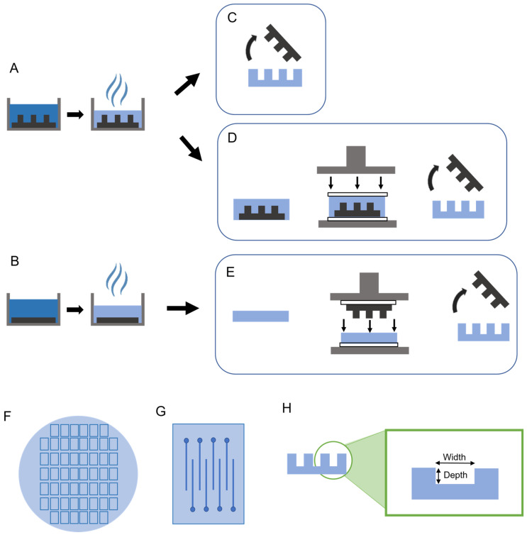
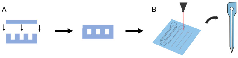
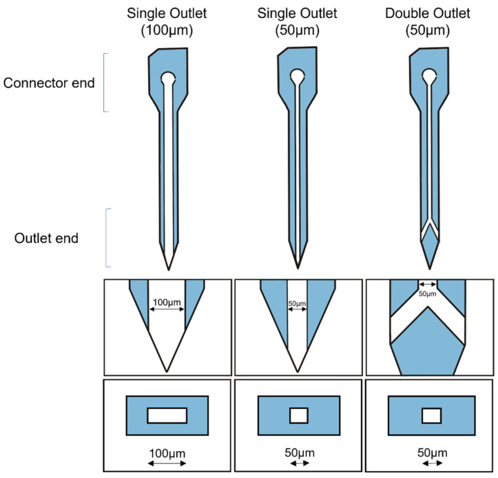
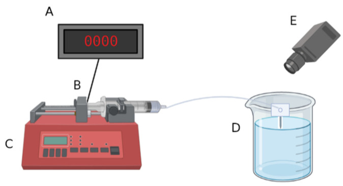
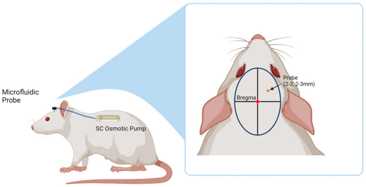
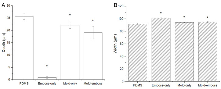
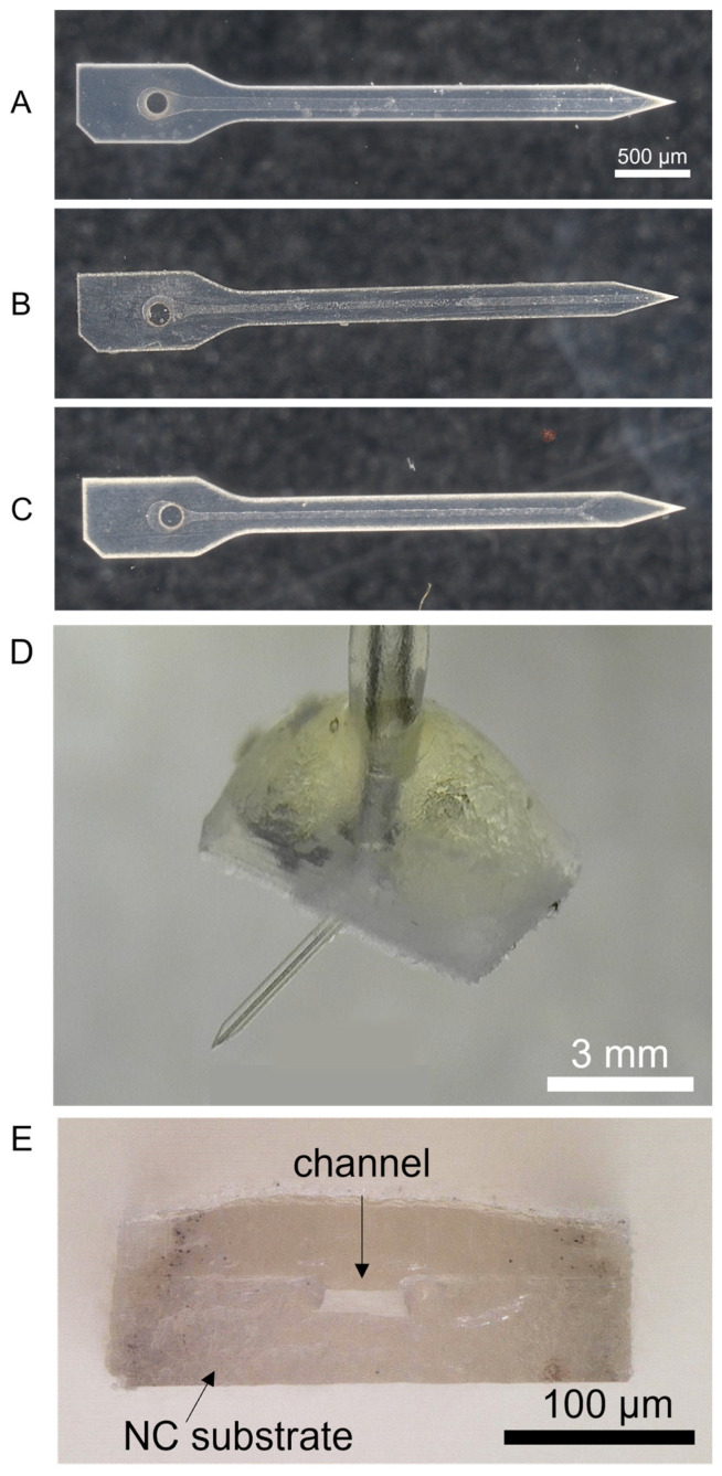
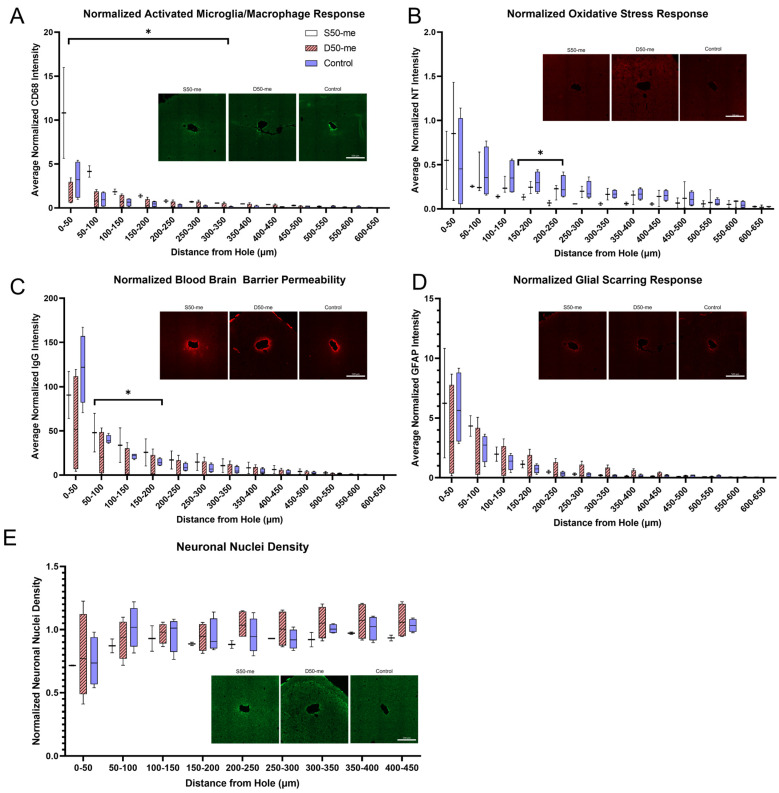
Intracortical neural probes are both a powerful tool in basic neuroscience studies of brain function and a critical component of brain computer interfaces (BCIs) designed to restore function to paralyzed patients. Intracortical neural probes can be used both to detect neural activity at single unit resolution and to stimulate small populations of neurons with high resolution. Unfortunately, intracortical neural probes tend to fail at chronic timepoints in large part due to the neuroinflammatory response that follows implantation and persistent dwelling in the cortex. Many promising approaches are under development to circumvent the inflammatory response, including the development of less inflammatory materials/device designs and the delivery of antioxidant or anti-inflammatory therapies. Here, we report on our recent efforts to integrate the neuroprotective effects of both a dynamically softening polymer substrate designed to minimize tissue strain and localized drug delivery at the intracortical neural probe/tissue interface through the incorporation of microfluidic channels within the probe. The fabrication process and device design were both optimized with respect to the resulting device mechanical properties, stability, and microfluidic functionality. The optimized devices were successfully able to deliver an antioxidant solution throughout a six-week in vivo rat study. Histological data indicated that a multi-outlet design was most effective at reducing markers of inflammation. The ability to reduce inflammation through a combined approach of drug delivery and soft materials as a platform technology allows future studies to explore additional therapeutics to further enhance intracortical neural probes performance and longevity for clinical applications.
Keywords: drug delivery; mechanically adaptive; microfabrication; microfluidic; neural interface; polymer.
Conflict of interest statement
The authors declare no conflict of interest.
Figures
Similar articles
-
Effects of Micromachining on Anti-oxidant Elution from a Mechanically-Adaptive Polymer.J Micromech Microeng. 2024 Feb 20;34(3):10.1088/1361-6439/ad27f7. doi: 10.1088/1361-6439/ad27f7. J Micromech Microeng. 2024. PMID: 38586082 Free PMC article.
-
Mechanically adaptive and deployable intracortical probes enable long-term neural electrophysiological recordings.Proc Natl Acad Sci U S A. 2024 Oct;121(40):e2403380121. doi: 10.1073/pnas.2403380121. Epub 2024 Sep 27. Proc Natl Acad Sci U S A. 2024. PMID: 39331412 Free PMC article.
-
Ultra-miniature ultra-compliant neural probes with dissolvable delivery needles: design, fabrication and characterization.Biomed Microdevices. 2016 Dec;18(6):97. doi: 10.1007/s10544-016-0125-4. Biomed Microdevices. 2016. PMID: 27778225
-
Multifunctional Fibers as Tools for Neuroscience and Neuroengineering.Acc Chem Res. 2018 Apr 17;51(4):829-838. doi: 10.1021/acs.accounts.7b00558. Epub 2018 Mar 21. Acc Chem Res. 2018. PMID: 29561583 Review.
-
Flexible, Penetrating Brain Probes Enabled by Advances in Polymer Microfabrication.Micromachines (Basel). 2016 Oct 4;7(10):180. doi: 10.3390/mi7100180. Micromachines (Basel). 2016. PMID: 30404353 Free PMC article. Review.
Cited by
-
In Vivo Characterization of Intracortical Probes with Focused Ion Beam-Etched Nanopatterned Topographies.Micromachines (Basel). 2024 Feb 17;15(2):286. doi: 10.3390/mi15020286. Micromachines (Basel). 2024. PMID: 38399014 Free PMC article.
-
Effects of Micromachining on Anti-oxidant Elution from a Mechanically-Adaptive Polymer.J Micromech Microeng. 2024 Feb 20;34(3):10.1088/1361-6439/ad27f7. doi: 10.1088/1361-6439/ad27f7. J Micromech Microeng. 2024. PMID: 38586082 Free PMC article.
References
-
- Association for Computing Machinery Special Interest Group on Accessible Computing; Proceedings of the ASSETS ’07 Ninth International ACM SIGACCESS Conference on Computers and Accessibility; Tempe, AZ, USA. 15–17 October 2007; New York, NY, USA: Association for Computing Machinery; 2007.
Grants and funding
LinkOut - more resources
Full Text Sources
