Review
. 2023 Jun 1;12(1):134.
doi: 10.1038/s41377-023-01119-0.

Photonic structures in radiative cooling

Affiliations
Review

Photonic structures in radiative cooling

Minjae Lee et al. Light Sci Appl. .

Abstract

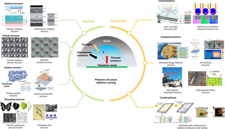
Radiative cooling is a passive cooling technology without any energy consumption, compared to conventional cooling technologies that require power sources and dump waste heat into the surroundings. For decades, many radiative cooling studies have been introduced but its applications are mostly restricted to nighttime use only. Recently, the emergence of photonic technologies to achieves daytime radiative cooling overcome the performance limitations. For example, broadband and selective emissions in mid-IR and high reflectance in the solar spectral range have already been demonstrated. This review article discusses the fundamentals of thermodynamic heat transfer that motivates radiative cooling. Several photonic structures such as multilayer, periodical, random; derived from nature, and associated design procedures were thoroughly discussed. Photonic integration with new functionality significantly enhances the efficiency of radiative cooling technologies such as colored, transparent, and switchable radiative cooling applications has been developed. The commercial applications such as reducing cooling loads in vehicles, increasing the power generation of solar cells, generating electricity, saving water, and personal thermal regulation are also summarized. Lastly, perspectives on radiative cooling and emerging issues with potential solution strategies are discussed.


Conflict of interest statement

The authors declare no competing interests.

Figures

Fig. 1
Fig. 1. Outline for radiative cooling.
Reproduced with permission. Copyright 2019, American Chemical Society, Reproduced with permission. Springer Nature¸ Reproduced with permission. Copyright 2015, Wiley-VCH, Reproduced with permission. Copyright 2017, Wiley-VCH, Reproduced with permission. Copyright 2022, Elsevier, Reproduced with permission. Copyright 2019, Wiley-VCH, Reproduced with permission. Copyright 2021, Wiley-VCH, Reproduced with permission, Copyright 2022, Royal society of chemistry, Reproduced with permission. Copyright 2015, AAAS, Reproduced with permission. Copyright 2018, Wiley-VCH, Reproduced with permission. Copyright 2022, ACS, Reproduced with permission. Copyright 2021, Wiley-VCH, Reproduced with permission. Copyright 2022, Springer Nature, Reproduced with permission. Copyright 2021, Wiley-VCH, Reproduced with permission. Copyright 2021, KeAi, Reproduced with permission. Copyright 2022, Cell press
Fig. 2
Fig. 2. Fundamentals of radiative cooling.
a Frozen iced on leaf in autumn. Reproduced with permission. Copyright, Adobe Stock b Daytime radiative cooling heat exchange process. c Energy balance of radiative cooling d Solar spectra and terrestrial radiation spectra, respectively, at sea level and atop the atmosphere. e absorption spectra of gases in solar and mid-IR range. d, e Reproduced with permission. Copyright 2018, AAAS. f Emissivity spectra of broadband and selective emitter. Reproduced with permission. Copyright 2020, MDPI
Fig. 3
Fig. 3. Photonic concepts for radiative cooling.
a Distributed Bragg Reflector structure b Fabry–Perot structure c Heat dissipation as thermal energy due to the enhanced emissivity resulting from surface phonon polaritons. Reproduced with permission. Copyright 2019, Wiley-VCH
Fig. 4
Fig. 4. Multilayer structure of daytime radiative coolers.
a Scanning electron microscope (SEM) image of seven multi layers of SiO2 and HfO2 on the top of Ag (left) emissivity in the mid-IR wavelengths (right). Reproduced with permission. Copyright 2018, Springer Nature. b SEM image of alternating layers of Si and Si3N4 on the top of Al (left) emissivity of ZnSe in mid-IR wavelengths (red) emissivity of multilayer device in the mid-IR wavelengths (blue) (right). Reproduced with permission. Copyright 2018, Springer Nature. c Schematic of multilayer structure (left) measured (black) and calculated (red) emissivity of structure in the mid-IR range (right). Reproduced with permission. Copyright 2020, Elsevier B.V. d Schematic of tandem structure (left) emissivity spectra with SiO2 (line) and without SiO2 (dot) in the mid-IR range (right). Reproduced with permission. Copyright 2019, American Chemical Society. e Schematic of multilayer structure (left) simulated (red) and measured (blue) emissivity in the mid-IR range and black body radiation at 300 K (black) (right). Reproduced with permission. Copyright 2018, Optical Society of America. f Schematic of multilayer structure and fabricated sample (left) measured (red) and simulated (black) emissivity in the mid-IR range (right). Reproduced with permission. Copyright 2020, American Chemical Society. g The spectral emissivity/absorptivity of (i), (ii), (iii), and (iv). Reproduced with permission. Copyright 2019, AIP
Fig. 5
Fig. 5. Periodic structure of daytime radiative coolers.
a Schematic of the radiative cooler structure with quartz bar on top of silicon nanowire (inset) the emissivity/absorptivity spectrum of the combined structure. Reproduced with permission. Copyright 2013, AIP. b Schematic of radiative cooler structure comprising SiC and quartz (inset) the emissivity spectrum of the structure. Reproduced with permission. Copyright 2013, ACS. c Schematic structure of the pyramidal multilayer (left) simulated emissivity of pyramidal multilayer cooler (right). Reproduced with permission. Copyright 2019, OSA. d Design of conical multilayer (left upper) SEM images of conical multilayer (left lower) calculated emissivity of conical multilayer for different bottom diameter (right). Reproduced with permission. Copyright 2015, Wiley-VCH. e Schematic of radiative cooler structure (left) Emissivity of the experimental (solid) and simulated (dashed) structure with different lengths, L = 750 nm (blue) and 1350 nm (red) (right). Reproduced with permission. Copyright 2017, ACS. f SEM image of the fabricated structure (inset), simulated (dot), and measured (line) emissivity of the fabricated structure. Reproduced with permission. Copyright 2017, Wiley-VCH. g SEM image of a colloidal crystal of 8 µm sphere (inset) reflectivity and emissivity spectra of soda lime glass (black) and crystal sphere (gray). Reproduced with permission. Copyright 2019, Wiley. h Schematic of the nano micro grating structure (inset) thermal emissivity spectra of cooler with glass nano-micro grating (red), with glass film (green), and bare doped Si (black). Reproduced with permission. Copyright 2021, Springer Nature
Fig. 6
Fig. 6. Random structure of daytime radiative coolers.
a Schematic of the glass particle in the polymer on the Ag (left) thermal emissivity spectra of cooler (right). Reproduced with permission. Copyright 2017, AAAS. b Schematic of the fabricated rod-like particle (left) schematic of the light scattering (middle) the reflectivity spectra of particle coating (red) and commercial white (blue) and gray (purple) paint (right). Reproduced with permission. Copyright 2022, Elsevier. c Schematic of AAO on the Al substrate (upper) SEM image of section view of AAO and measured emissivity of AAO sample (lower). Reproduced with permission. Copyright 2018, Elsevier B.V d Schematic of the nanopore fiber and microsphere (left) emissivity of membrane cooler in mid-IR range (right upper) reflectance of membrane cooler in solar spectrum (right lower). Reproduced with permission. Copyright 2020, Wiley-VCH. e Schematic of the ultra-broadband radiative cooler structure (inset) the reflectivity and emissivity spectrum of the cooler with metasurface (black) the emissivity spectrum of the cooler without metasurface (red). Reproduced with permission. Copyright 2021, IOP. f Section view of porous cylinder structure (left) simulated emittance spectra of shell and hollow cylinder structure (right). Reproduced with permission. Copyright 2019, The Royal Society of Chemistry
Fig. 7
Fig. 7. Bioinspired regenerated structure of daytime radiative cooler.
a Sahara silver ants; SEM and schematic images of the its hairs (left) reflectivity of silver ants body surface with hair (red) and without hair (black) in solar spectrum (middle) the mid-IR range (right). Reproduced with permission. Copyright 2015, AAAS. b A male N.gagas and SEM image of its fluffs and bioinspired regenerated radiative cooler (left) reflectivity of silver ants body surface with hair (red) and without hair (black) in solar spectrum (middle) and the mid-IR range (right). Reproduced with permission. Copyright 2021, National Academy of Science. c Photograph and microscopic image of cocoon (left) reflectance and emittance spectra of bioinspired regenerated cooler (right). Reproduced with permission. Copyright 2018, Springer Nature. d Photograph of a male Archaeoprepona demophon and SEM image of the its grating and pore structure (left); reflectance and emittance spectra of bioinspired regenerated cooler (right). Reproduced with permission. Copyright 2022, RSC. e Photograph of a female C.atrata and cross section view of microspike (left) measured reflectivity and emissivity of bioinspired regenerated cooler and TPU film as reference (right). Reproduced with permission. Copyright 2021, Wiley-VCH
Fig. 8
Fig. 8. Colored photonic radiative coolers.
a Schematic of the colored passive radiative cooler (left) section view of colored passive radiative cooler (middle) calculated (dash line) and measured (line) emissivity in mid-IR range (right). Reproduced with permission. Copyright 2018, Wiley-VCH. b Schematic structure of the designed colored radiative cooler (left) displayed color by adjusting thickness of silver and DBR (middle) emissivity (red) reflectivity (black) of three colors in the mid-IR range (right). Reproduced with permission. Copyright 2019, ACS publications. c SEM image of the “cold” and “hot” structures of same color (left) absorptivity spectra of ‘cold’ (blue line) and “hot” (red line) with the pink (pink dashed) black (black dashed) paints (middle) emissivity spectra of cold’ (blue line) and ‘hot’ (red line) with the pink (pink dashed) and black (black dashed) paints (right). Reproduced with permission. Copyright 2018, Springer Nature. d Schematic of retroreflection-induced color with PS microsphere of 15 (red), 8 (green), 3 (blue) um respectively (left) emissivity spectra of blue colored cooler and blue commercial paint (middle) optical and IR image of “KNU” (right). Reproduced with permission. Copyright 2022, ACS publication. e Schematic of opal colored radiative cooler with silica nanosphere of 290 (red), 240 (green), 290 (blue) nm (left) emissivity spectra of opals in the solar (middle) and mid-IR (right) ranges. Reproduced with permission. Copyright 2020, American Chemical Society
Fig. 9
Fig. 9. Transparent radiative coolers.
a Schematic design and optical image of fabricated of a transparent radiative cooler (left) measured emissivity (black), transmittance (red), and reflectance (blue) spectra of the cooler in solar irradiation range (middle) measured emissivity of the cooler in the mid-IR range (right). Reproduced with permission. Copyright 2021, Wiley-VCH. b Schematic structure of a transparent radiative cooler (left) optical and IR image of NIR reflection with and without PDMS (middle) measured emissivity spectra of #1 and #2 in mid-IR range (right). Reproduced with permission. Copyright 2020, Elsevier. c Schematic deign of enhanced colored-preserving radiative cooling (ECRC) (left) optical and IR image of interior and exterior surfaces (middle) transmissivity and emissivity spectra of exterior surface (right upper) and interior surface (right lower). Reproduced with permission. Copyright 2022, Springer Nature. d Simulated 2D model with n-hexadecane infiltration (left) optical image of fabricated transparent cooler (middle) measured transmissivity and reflectivity of transparent cooler (right). Reproduced with permission. Copyright 2022, Wiley-VCH. e Optical image and schematic structure of transparent radiative cooler (left) transmissivity and emissivity of 8 mm glass and transparent cooler in the solar spectrum (middle) and mid-IR (right). Reproduced with permission. Copyright 2021, KeAi
Fig. 10
Fig. 10. Schematic structures of switchable radiative cooling.
a Schematic of combined switchable structure comprising bandpass filter on top and radiative cooler on the bottom (left) emissivity spectra of metallic (red) and insulating (blue) in the mid-IR range (right). Reproduced with permission. Copyright 2018, Optica publishing group. b Schematic of combined switchable structure comprising filter on top and trapezoidal multilayer cooler on the bottom (left) emissivity spectra of metallic (blue) and insulating (red) in the mid-IR range (right). Reproduced with permission. Copyright 2020, Optica publishing group. c Schematic of multinalyer photonic structure (inset) calculated emissivity spectra of dielectric (red) and metallic (blue). Reproduced with permission. Copyright 2018, ACS. d Schematic structure of switchable radiative cooler (inset left) emissivity and reflectivity spectra when VO2 is in metallic (left) and insulating (right). Reproduced with permission. Copyright 2021, OE. e Schematic structure with switchable cooler (inset) regulation of transmissivity and emissivity spectra at 20 °C (cold) and 90 °C (red) Reproduced with permission. Copyright 2021, AAAS. f Schematic structure of TARC (left) measured emissivity spectra of TARC at 15 °C (blue line) and 30 °C (red line) with calculated emissivity (dashed line) (right) Reproduced with permission. Copyright 2021, AAAS. g Schematic mechanism of switchable radiative cooler in cold (left upper) and hot (left lower) solar reflectivity spectra of glazing window in heating (red) and cooling (blue) (middle) emissivity spectra of glazing window with (blue) and without (green) BoPET film in cooling (right) Reproduced with permission. Copyright 2022, Elsevier
Fig. 11
Fig. 11. Photonic radiative cooling in applications.
a Schematic of transparent radiative cooler in the vehicle. Reproduced with permission. Copyright 2021, Wiley-VCH. b Schematic of hollow fiber radiative cooling in building. Reproduced with permission. Copyright 2021, ACS. c Schematic of transparent radiative cooler and self-cleaning in solar cell. Reproduced with permission. Copyright 2021, Elsevier. d Schematic of energy harvesting with radiative cooler and thermoelectric generator in night time. Reproduced with permission. Copyright 2019, Elsevier. e Schematic of the water harvesting device with radiative cooler. Reproduced with permission. Copyright 2018, Springer Nature. f Schematic of personal temperature regulation using radiative cooling. Reproduced with permission. Copyright 2018, Wiley-VCH

References

    1. Santamouris M. Cooling the buildings—past, present and future. Energy Build. 2016;128:617–638. doi: 10.1016/j.enbuild.2016.07.034. - DOI
    1. Steven Brown J, Domanski PA. Review of alternative cooling technologies. Appl. Therm. Eng. 2014;64:252–262. doi: 10.1016/j.applthermaleng.2013.12.014. - DOI
    1. Cook BI, et al. Global warming and 21st century drying. Clim. Dyn. 2014;43:2607–2627. doi: 10.1007/s00382-014-2075-y. - DOI
    1. Hossain MM, Gu M. Radiative cooling: principles, progress, and potentials. Adv. Sci. 2016;3:1500360. doi: 10.1002/advs.201500360. - DOI - PMC - PubMed
    1. Stark AK. Methods for rejecting daytime waste heat to outer space. Natl Sci. Rev. 2017;4:789–790. doi: 10.1093/nsr/nwx052. - DOI