. 2023 Jun 5;14(1):3237.
doi: 10.1038/s41467-023-39072-6.

Point singularity array with metasurfaces

Affiliations

Point singularity array with metasurfaces

Soon Wei Daniel Lim et al. Nat Commun. .

Abstract

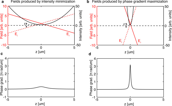
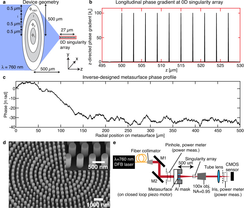
Phase singularities are loci of darkness surrounded by monochromatic light in a scalar field, with applications in optical trapping, super-resolution imaging, and structured light-matter interactions. Although 1D singular structures, like optical vortices, are common due to their robust topological properties, uncommon 0D (point) and 2D (sheet) singularities can be generated by wavefront-shaping devices like metasurfaces. With the design flexibility of metasurfaces, we deterministically position ten identical point singularities using a single illumination source. The phasefront is inverse-designed using phase-gradient maximization with an automatically-differentiable propagator and produces tight longitudinal intensity confinement. The array is experimentally realized with a TiO2 metasurface. One possible application is blue-detuned neutral atom trap arrays, for which this field would enforce 3D confinement and a potential depth around 0.22 mK per watt of incident laser power. We show that metasurface-enabled point singularity engineering may significantly simplify and miniaturize the optical architecture for super-resolution microscopes and dark traps.


Conflict of interest statement

S.W.D.L., J.S.P., A.H.D, M.L.M., and F.C. are the inventors on a relevant provisional patent application (application number: US20230021549A1) owned by Harvard University. The authors declare no other competing interests.

Figures

Fig. 1
Fig. 1. 0D singularity geometry.
a 0D singularities in 3D space are isolated points of vanishing intensity in a scalar field E, occurring when the real (blue) and imaginary (red) zero-isosurfaces of E intersect tangentially. b yz cross-sectional phase and (c) intensity profiles of the 0D singularity in (a). The dotted blue and red lines represent the real and imaginary zero-isolines of E on the plane, respectively. d Magnitude of the phase gradient ϕ in the yz plane, which is dominated by the minus z-directed phase gradient. The phase gradient diverges to infinity at the singularity position.
Fig. 2
Fig. 2. Comparison between two methods of producing 0D singularities: intensity minimization and phase gradient maximization.
Only field behavior along the optic axis (z axis) is shown for simplicity. a Real (Er) and imaginary (Ei) parts of scalar field E in the vicinity of a low intensity position with minimum intensity ϵ. Intensity minimization at z = 0 does not take the spatial distribution of fields around the low intensity point into account, producing fields with slowly varying Er and Ei through the minimum, thereby producing a broad intensity minimum. b On the contrary, since phase gradient maximization at z = 0 simultaneously minimizes the intensity there and maximizes the field slopes dErdz,dEidz passing through that point, the resultant intensity minimum is narrow. c The phase gradient peak through z = 0 for the field in (a) produced by intensity minimization there is typically much lower than that of phase gradient maximization, as depicted in (d), which plots the phase gradient for the field in (b).
Fig. 3
Fig. 3. Design and experimental realization of 0D singularity array.
a Geometry of the phase-only metasurface to generate the singularity array upon illumination by λ = 760 nm light. The Cartesian directions are also indicated. b Longitudinal (z) phase gradient along the optic axis at the 0D singularity array, demonstrating large (compared to the free-space wavenumber k0) and uniform phase gradients at the singularity locations. c Inverse-designed metasurface phase profile as a function of metasurface radial position that achieves the 0D singularity array. The phases have been unwrapped to show the long-range variation. d Scanning electron microscope image of the TiO2 nanopillars on SiO2 at the center of the fabricated metasurface that achieves the phase profile in (c). Inset: close-up of the nanopillars demonstrate vertical sidewalls. e Experimental setup to generate and characterize the 0D singularity array. Dotted lines indicate the positions of the pinholes and power meter used in characterizing the absolute transmission intensity.
Fig. 4
Fig. 4. Longitudinal intensity cuts for singularity array with ten on-axis 0D singularities.
The metasurface that produces this light field is located at z = 0. The color scales are adjusted to show the singular region with higher contrast; peak intensity values for each of the colormaps are indicates in the top right-hand corner. White arrows indicate the locations of the ten 0D singularities. a Numerically simulated xz cut for the ideal metasurface. The yz cut is identical due to the rotational symmetry of the light field about the optic axis. b Experimental xz cut and (c) experimental yz cuts for the fabricated metasurface light field, demonstrating good agreement to the simulated light field. d On-axis (x = y = 0) intensity comparison for numerical (black) and experimental (red) measurements. The axial displacement arises due to the experimental illumination wavelength of 760.9 nm being slightly longer than the target wavelength of 760 nm. e Experimental transverse (xy) intensity profiles at each of the singularity positions (bright hollow annulus surrounding the 0D singularity) and in-between the singularity positions (focused spot). The longitudinal cuts in (b, c) are obtained by stacking 1201 such transverse images.

References

    1. Dennis, M. R., O’Holleran, K. & Padgett, M. J. In Progress in Optics Vol. 53 (ed. Wolf, E.), 293–363 (Elsevier B.V., 2009).
    1. Dennis MR. Rows of optical vortices from elliptically perturbing a high-order beam. Opt. Lett. 2006;31:1325–1327. doi: 10.1364/OL.31.001325. - DOI - PubMed
    1. Lim SWD, Park J-S, Meretska ML, Dorrah AH, Capasso F. Engineering phase and polarization singularity sheets. Nat. Commun. 2021;12:4190. doi: 10.1038/s41467-021-24493-y. - DOI - PMC - PubMed
    1. Gerchberg RW, Saxton W. Phase determination for image and diffraction plane pictures in the electron microscope. Optik. 1971;34:275–284.
    1. Gerchberg RW, Saxton WO. A practical algorithm for the determination of phase from image and diffraction plane pictures. Optik. 1972;35:237–246.