Review
. 2023 May 30;13(11):1763.
doi: 10.3390/nano13111763.

Carbon Nanocomposites in Aerospace Technology: A Way to Protect Low-Orbit Satellites

Affiliations
Review

Carbon Nanocomposites in Aerospace Technology: A Way to Protect Low-Orbit Satellites

Janith Weerasinghe et al. Nanomaterials (Basel). .

Abstract

Recent advancements in space technology and reduced launching cost led companies, defence and government organisations to turn their attention to low Earth orbit (LEO) and very low Earth orbit (VLEO) satellites, for they offer significant advantages over other types of spacecraft and present an attractive solution for observation, communication and other tasks. However, keeping satellites in LEO and VLEO presents a unique set of challenges, in addition to those typically associated with exposure to space environment such as damage from space debris, thermal fluctuations, radiation and thermal management in vacuum. The structural and functional elements of LEO and especially VLEO satellites are significantly affected by residual atmosphere and, in particular, atomic oxygen (AO). At VLEO, the remaining atmosphere is dense enough to create significant drag and quicky de-orbit satellites; thus, thrusters are needed to keep them on a stable orbit. Atomic oxygen-induced material erosion is another key challenge to overcome during the design phase of LEO and VLEO spacecraft. This review covered the corrosion interactions between the satellites and the low orbit environment, and how it can be minimised through the use of carbon-based nanomaterials and their composites. The review also discussed key mechanisms and challenges underpinning material design and fabrication, and it outlined the current research in this area.

Keywords: LEO satellites; carbon nanomaterials; nanotechnology; satellite corrosion; space environment; spacecraft.


Conflict of interest statement

The authors declare no conflict of interest.

Figures

Figure 1
Figure 1
(a) Atmospheric density and composition at different altitudes. The highly reactive atomic oxygen (AO) is the predominant chemical species in VLEO. Data from N.H. Crisp et al., 2022 [2]. (b) Number of satellites on orbit based on the database of UCS. Data from J. Wu et al., 2022 [11] © 2022 Elsevier.
Figure 3
Figure 3
Residual atmosphere at VLEO inside and outside of a satellite. (a). Intake device collects the rarefied gas and supplies it to a thruster. The system can also include a thermalization chamber between the intake device and the ionization chamber of the thruster (not shown in this scheme). Reprinted with permission from P. Zheng et al., 2022, [23]. (b) Pressure distribution in the intake device at an altitude of 150 km. A case when the focal point of parabola is located inside the discharge channel of the thruster. The pressure rises significantly in some areas around the satellite part, and oxygen could cause significant damage, in particular in hot areas of the intake devices and thrusters. Reprinted with permission from F. Romano et al., 2021, [24]. External geometry of VLEO satellites also needs to be optimised to decrease drag. At the VLEO altitude range, the gas is rarefied and the free molecular flow should be considered, when the mean free pass of particles exceeds the size of a satellite. (c) Illustrates the three types of optimised shapes (marked ‘1’, ‘2’, and ‘3’) of spacecraft, and (d) shows the simulated pressure distribution around the body for the typical VLEO conditions. A significant increase in the particle densities over some areas could cause enhanced material damage. Reprinted with permission from F. Hild et al., 2022, [25]. © 2022 IAA. Published by Elsevier.
Figure 4
Figure 4
The impact of the collision with 1.59 mm aluminium spheres on the integrity of solar arrays. The experiment used sphere velocities typically detected in the collisions between space debris and satellites. Reprinted with permission from H. Krag et al., 2017 [32]. © 2017 Elsevier.
Figure 7
Figure 7
Lab-based AO corrosion experiments and facilities. (a) Radio-frequency system. (b) The measured current is dependent on the negative bias (inset illustrates the distribution of electron energy). (c) The ultra-violet flux and optical emission spectroscopy (OES intensity). Reproduced with permission from Shpilman et al. [49]. © AIP. (d,e) Scheme of the experiment and the measured mass loss due to AO exposure. The designed system ensures regulation of the AO flux, thus enabling modelling the AO impact at various altitudes. Reproduced with permission from Huang et al. [50]. Copyright AIP. (f,g) The ground test of a space materials degradation detector before and after exposure to an AO flux. Reproduced with permission from Verker et al., 2020 [51]. © Elsevier.
Figure 11
Figure 11
Understanding the interaction of AO with graphene: Schematic of the bonding conditions of the sites that AO fly by after the impact on C atom site with φ values (a) 0°, (b) 30°, (c) 90°. AO could be both scattered and adsorbed by graphene after impacting the C atom site. Reprinted with permission from Li et al., 2023 [56] © 2019 Elsevier.
Figure 12
Figure 12
Graphene/SiO2 nanoparticles composite to enhance atomic oxygen corrosion resistance. (a) Schematic of the mechanism that (a) graphene flakes and (b) graphene flakes/SiO2 nanoparticles composite mitigate atomic oxygen corrosion of polyimide. (c) Barrier and bonding effects between graphene flakes and atomic oxygen. (d) Mass loss of graphene flakes/SiO2 nanoparticles composite film after atomic oxygen exposure. Reprinted with permission from Zhao et al., 2021 [88] © 2021 Elsevier.
Figure 13
Figure 13
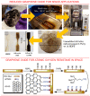
Graphene oxide and reduced graphene for space applications. Top panel: Schematics of the process used for composite fabrication, consisting of premixing (a), melt compounding (b), melt pressing (c,d) and, finally, forming of the samples (e). Reprinted with permission from Seibers et al., 2021 [93]. © 2019 Society of Plastics Engineers. Bottom panel: hierarchical reinforcement by grafting graphene oxide onto poly(p-phenylene benzobis-oxazole fibres for resistance to AO-induced degradation in space. Reprinted with permission from Chen et al., 2015 [95]. © 2015 Elsevier.
Figure 2
Figure 2
Atmospheric density around the globe is not a constant value. (a) Atmospheric density measured by the spherical Qiu Qiu (QQ) satellite. The density changes by a factor of 3–4 during, thus potentially representing a significant disturbance for satellites occupying these orbits. Reprinted from Y. Sun et al., 2022 [14] under terms and conditions of the CC BY license. (b) Along with the global un-uniformity of the atmospheric density, it also changes with the seasons due to differences in solar radiation. Reprinted from G. Chen et al., 2023 [13] under terms and conditions of the CC BY license.
Figure 5
Figure 5
Proposed mechanism by which alkylated-reduced graphene oxide additive affords protection against AO damage to a polymer matrix. The uniform dispersion of ultra-high modulus RGO in the polymer matrix can effectively mitigate the impact of high-energy AO, which effectively protects the polymer matrix from direct impact (route 1). Reprinted with permission from Xie et al., 2015 [40] © 2015 Elsevier.
Figure 6
Figure 6
In-orbit material experiment project. Based on a 2U (double-unit) CubeSat, this system incorporates several material experiments, namely CiREX (Carbon Nanotubes—Resistance Experiment), Flux-(Phi)-Probe-Experiment (FIPEX) and Thermoelectric-Generator-Experiment (TEG). Reprinted with permission from Abbe et al., 2019 [43]. © 2018 COSPAR. Published by Elsevier.
Figure 8
Figure 8
Interaction of AO with carbon: understanding the mechanism via simulations. (a,b) Evolution of kinetic energy during the collision between AO and C atom site of graphene could be split to the three stages. (c) Snapshots of several points marked in (b). Reprinted with permission from Li et al., 2023 [56] © 2022 Elsevier.
Figure 9
Figure 9
AO resistance mechanism of multiwalled carbon nanotubes. (a) Scheme of the test in space environment; (b) pristine hydrogen-rich benzoxazine; (c) small amount of multiwalled carbon nanotubes/hydrogen-rich benzoxazine, and (d) large amount of multiwalled carbon nanotubes/hydrogen-rich benzoxazine. Reprinted with permission from Cha et al., 2022 [85] © 2022 Elsevier.
Figure 10
Figure 10
Influence of atomic oxygen exposure on carbon nanotube–polyhedral oligomeric silsesquioxane–polyimide film. (a) Erosion yields of the composite films and Kapton H as a function of atomic oxygen fluence. (b) The response of sheet resistivity of the composite films to changes in atomic oxygen fluence. Reprinted with permission from Atar et al., 2021 [85]. © ACS.
Figure 14
Figure 14
Top panel: Carbon nanofiber-reinforced composites for aerospace applications. (a) Illustrates the microstructure of the material after carbon coating followed with the reduction. (b) Surface of the fracture with the carbon nanofibers clearly visible. Reprinted with permission from Barcena et al., 2010 [96] © Wiley. Bottom panel: Atomic oxygen and UV protection for carbon fibre composite materials. (c) The focused ion beam was used to prepare the cross-section of the carbon fibre-reinforced polymer–moisture and outgassing barrier material system. The top protective layers delaminated due to interruption of the process in vacuum (shown in the blue ring on the photo). The red circle shows the pinholes by the atomic oxygen exposure. (d) same view of the focused ion beam cross-section made in the uninterrupted process, without any delaminations and holes. Reprinted with permission from Smith et al., 2021 [97] © 2021 ACS.

References

    1. Allen C.S., Giraudo M., Moratto C., Yamaguchi N. Chapter 4—Spaceflight environment. In: Sgobba T., Kanki B., Clervoy J.-F., Sandal G.M., editors. Space Safety and Human Per-formance. Butterworth-Heinemann; Oxford, UK: 2018. pp. 87–138.
    1. Crisp N.H., Rojas A.M., Roberts P.C.E., Edmondson S., Haigh S.J., Holmes B.E.A., Oiko V.T.A., Sinpetru L.A., Smith K.L., Arcos A., et al. Experimental Results from the Satellite for Orbital Aerodynamics Research (SOAR) Mission; Proceedings of the 73rd International Astronautical Congress (IAC); Paris, France. 18–22 September 2022; pp. 1–9.
    1. Meseguer J., Pérez-Grande I., Sanz-Andrés A. 3—Keplerian orbits. In: Meseguer J., Pérez-Grande I., Sanz-Andrés A., editors. Spacecraft Thermal Control. Woodhead Publishing; Cambridge, UK: 2012. pp. 39–57.
    1. Levchenko I., Keidar M., Cantrell J., Wu Y.-L., Kuninaka H., Bazaka K., Xu S. Explore space using swarms of tiny satellites. Nature. 2018;562:185–187. doi: 10.1038/d41586-018-06957-2. - DOI - PubMed
    1. Levchenko I., Goebel D.M., Bazaka K. Electric propulsion of spacecraft. Phys. Today. 2022;75:38–44. doi: 10.1063/PT.3.5081. - DOI - PubMed

LinkOut - more resources